
Downloaded from hlayiso.com
*GRDSE1*
Skip to contentQuestion paper 
--55d6af85-d3ce-4134-b1cb-91d1b25d8820/v1-32b052434a49c795c80f/card.webp)
View all

%20June%202024%20Question%20Paper_hlayiso.com_--5258bc0e-6828-4661-a7e7-9553fbae9844/v1-d830123ee9ddaa89f5ae/card.webp)
Engineering Graphic And Design Grade 12 Eastern Cape Mock 2019 QP
Grade 12 Engineering Graphic And Design question paper from the Eastern Cape Mock Exam 2019, 6 pages. Read online or get the free PDF download, memo linked when available.
Engineering Graphic And Design · Grade 12 · Eastern Cape Mock Exam · 2019. Question paper, 6 pages. Read online or download the PDF.
- Subject
- Engineering Graphic And Design
- Grade
- Grade 12
- Document type
- Question paper
- Year
- 2019
- Exam period
- Eastern Cape Mock Exam
- Curriculum
- CAPS
- Pages
- 6
- File size
- 1.6 MB
Loading document…
Loading document…
1 of 6
Document textSearch extracted text and jump to a page.
Engineering graphics and design / P1
PRIMARY SCHOOL
STAND 4199
LAND SURVEYOR'S CERTIFICATE,
OF THE SIDE LENGTHS AND.
CORNER HEIGHTS ON STAND 4200)
SURVEYED ON 2018-12-20
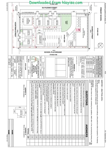
QUESTION 1: ANAL’
EC / September 2019
ICAL (CIVIL)
Given:
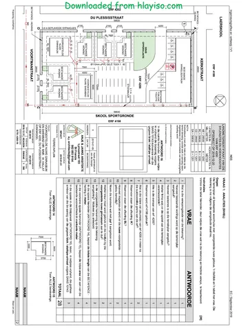
The site plan for existing dwellings with new proposed buildings, a title panel and a table of questions. The drawing
has not been prepared to the indicated scale.
LENGTHS IN |CORNER HEIGHTS IN
MILLIMETRES METRES Instructions:
BETAFENCE - CHURCH STREET AB = 28500 A= 1200 Complete the table below by neatly answering the questions, which refer to the accompanying drawing and title
FENCING an 28500 { BC = 56830 B= 1200 panel [28]
NE CD = 28500 C= 1201
ps = =
od ; oe seeso [__9= 1201 QUESTIONS ANSWERS
EXISTING - Contractors must verify all di id i it
(4 | SHOPPING CENTRE eomaetors: must very ‘Commencing. work 1 | What is the reference code of the drawing? 1
| ! Sees ee, DP motile’ Immediately of any » | How many existing dwellings are indicated on the site 1
mICSICSICSICS ® ARCHITECT'S SIGNATURE plan?
L 1 CLIENT'S SIGNATURE 3 | How many loading zones are indicated on the site plan? 4
3 | lla | l& hi ANSWER 16 4 | Which company was responsible for setting up the site 1
3 | fd EXISTING In the space provided below, draw, in plan?
4 PUBLIC | | neat freehand, the top view of the
Tonets [YF SANS 10143 convention for a block/| | 5 | Whois the owner of stand 4200? 1
TAR stall type urinal
SURFACE 6 | What is stand 4198 used for? 1
STAND 4200 z_| Whatis the total fall slope) of stand 4200 in meters to the 5
south eastern boundary of the stand?
24m 2 8 | What does the abbreviation IC stand for? 1
| BRICK WALL 2
a — EXISTING | | fe} 9 | What does the abbreviation BL stand for? 1
glu oweuwe pe} me
3 | ie Niel a = 4o | How many inspection eyes are needed for the new 2
2 | x3 ESI Te as 2 proposed building?
25° — ‘5 2
blo 1 g— __ —__| a§ 11 | Name the feature that is indicated by arrow 1. 1
mn Ie]
2 _existins |i) 2— ~~ J 8 What colour should be used to indicate the sewer line at
8 DWELLING — — —_ 12 | th d im? 2
wy iflz | FA e new proposed gymnasuim
a 1) |&—, 72000 a 4g | Has the proposed revision been made on the drawing? >
2 8p 3000 1 [2010-01-09 | ew syrnasiam ovr he Motivate your answer.
\! PROPOSED NEW REVISION | DATE DESCRIPTION 14 In the space below (ANSWER 14), determine the total length of the BETAFENCE-fence in 4
— fasting |)! |g] |gl|sumivs poot metres.
eo DWELLIN 3 8
3 - LE Le| ANJE ‘oa tyme suet 4g | In the provided space below (ANSWER 15), determine the total area of one of the existing |
IC. i i
===> - -—i" ‘St Francis dwellings in square meters.
QP 4 [reste JIE Ree | a2 893 9154 ‘ 4g | I" the provided space in the tile panel (ANSWER 16), draw in neat freehand, the graphical a
a1 | qh FP ' aj. architects@gmail.com symbol of the top view of the given block / stall type urinal according to SANS 10143.
ay | new existe iI easti PANTED BY DATE OF PANT
1-4 || PROPOSED j | DWELLING I DWELLING | | IMPACT 2019-01'31 TOTAAL} 28
Bhy || Srimasim an 1 DRAWING THLE
5400
Z| | Jj Lo! | SITE PLAN ANSWER 14° pO, ANSWER 15
E | I | Show ALL calculations. Show ALL calculations.
efy | _BL1600_ | rs SH ee
7 1 PROPOSED NEW GYMNASIUM AND EXISTING 3
a Lo SWIMMING POOL FOR MR. W. HALLAT| g] | OWELLING | 5
c ON STAND 4200, DU PLESSIS STREET| ze
BETAFENCE - —*# 28500 ™ IRKW ccm DRAWING NUMBER
FENCING PR "
VOORTMAN STREET crue NG =
ye ee oe | aan EES] SRE [2200
1 r 2018-12-31] KEAGON | DWANE | 1: 300 NAME
REFERENCE CODE
SITE- 4200-19 NAME [2
Copyright reserved
Please tum over
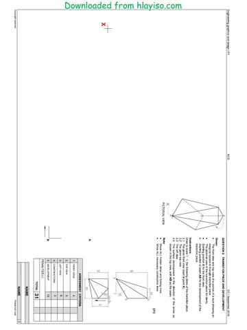
QUESTION 2: TRANSITION PIECE AND DEVELOPMENT
un apap Downloaded from hlayiso.com srsuamnns
x —/
PICTORIAL VIEW.
Given:
* The front view and top view of a portion of a duct showing an
irregular square-to-triangle transition piece.
* The pictorial view of the transition piece for clarity.
* Starting position X for the front view.
* Starting position of seam AB for the development of the
transition piece.
Instructions:
Draw to scale 1 : 1, the following views of the transition piece:
2.1. The given front view (start at point X),
2.2 The given top view.
2.3 The left view.
24 The surface development in the direction of the arrow as
shown in the top view, with AB as the seam
Note:
* — Show ALL hidden detail and folding lines.
* Show ALL necessary construction lines.
[31]
A
ASSESSMENT CRITERIA
1 | FRONT ViIEW 4
2 | Top view 5
3 | LEFT view 6
4 | CONSTRUCTIONS 3
B 5 | DEVELOPMENT 13
PENALTIES (-)
TOTAL | 34
NAME
NAME [3
Copyright reserved
Please tum over
Engineering graphics and design / P41 EC / September 2019
QUESTION 3: PERSPECTIVE
Given:
* Views of a garage and washroom and the
information needed to draw a two-point
perspective drawing.
* — Anauxiliary view.
PP - Picture plane
HL - Horizon line
GL - Ground line
SP - Station point
AUXILIARY VIEW
Instructions:
Complete the perspective drawing
Align the drawing sheet with the ground line (GL).
Determine and label the vanishing points.
Show ALL necessary construction.
NO hidden detail is required. [41]
ASSESSMENT CRITERIA
1| CONSTRUCTION AND VPs | 6
2 | ROOF 14
3 | WALLS 5
4 | DOORS AND WINDOW of
PP
5 | CIRCLE AND RAMP 63
TOTAL | 44
HL HL
GL GL
NAME
SP NAME [4
Please tum over
Copyright reserved
Downloaded from hlayiso.com
Engineering graphics and design / P1 EC / September 2019
QUESTION 4: CIVIL DRAWING
Given: 280 x 80 x 10 mm BARGE BOARD RAINES PoGAND WINESIGeM EEUU
© The incomplete south view of a cottage, showing the walls,
the windows, the door opening, the roof and notes
© The incomplete floor plan showing the roof line, walls,
position of the doors, windows, fixtures and electrical
layout.
* A schematic diagram of a roof truss and roof notes
© The incomplete foundation and wall detail
* Room designations and floor finishes
* A door and window schedule
* A table of sanitary fixtures
* A table of roof components
* A table of electrical symbols
* A table of rainwater items
* The floor plan of the cottage, drawn to scale 1 : 50 and the
incomplete foundation of the detailed section, drawn to
scale 1 : 20 on page 6
Instructions:
Answer this question on page 6.
4.1. Use the given incomplete floor plan to draw, in
first-angle orthographic projection and to scale 1 : 50,
the following views of the cottage:
4.1.1 THE COMPLETE FLOOR PLAN
Add the following features to the drawing:
* ALL doors and windows
* ALL sanitary fixtures as indicated by abbreviations
* ALL electrical fittings as indicated by the numbers
* ALL hatching detail
4.1.2 THE COMPLETE SOUTH VIEW
Show the following features on the drawing:
* The outside walls, steps and window detail
* The roof detail, including the roof cap, barge boards,
fascia boards, gutter and rain- water down pipes
* The finished floor level
4.2 Inthe space provided on page 6, using the incomplete
foundation and break line, draw, to scale 1; 20, a
DETAILED SECTION on cutting plane A-A of the area in
the ellipse shown on the incomplete floor plan
* Show the following features on the drawing:
* The complete detail of the foundation, external wall
with window detail, shower wall and relevant sanitary
fixtures.
* The roof detail, including the barge board, fascia
board, gutter and rain water down-pipe
* ALL hatching detail. ONLY the substructure hatching
may be drawn in neat freehand.
Label the following:
© The south elevation
© The room designations and floor finishes.
* Ground level, finished floor level and damp proof course
(Use the correct abbreviations and show them on ALL
the relevant views)
NOTE:
ALL drawings must comply with the guidelines and
graphical symbols as contained in the SANS 10143.
[100]
47:
4400
ROOF NOTES:
i
INCOMPLETE SOUTH
INCOMPLETE FLOOR PLAN
30° ROOF PITCH
114 x 38 mm ROOF TRUSSES ON 114 x 38 mm WALL PLATES
ROOF COVER: 20 mm IBR SHEETING ON 75 x 50 mm PURLINS @ 1000 mm cic
280 x 80 x 10 mm BARGE BOARD ON GABLE ENDS AND OVERHANG IS IN LINE
WITH THE GUTTERS. TOTAL OVERHANG IS 300 mm (GUTTERS INCLUDED) 240
220 x 20 mm FASCIA BOARD ON ALL SIDES
150 x 100 mm GUTTERS ON ALL SIDES WITH 2100 mm RAINWATER DOWN-PIPES L
ROOF CAPS MUST BE MOUNTED ON THE ROOF PITCH.
9 mm CEILING BOARD ON 38 x 38 mm BRANDERING @ 400 mm cic
EQUAL
| Equal | ecquar |
EQUAL
SCHEMATIC DIAGRAM OF THE ROOF
—
GROUND LEVE!
220 x 20 mm FASCIA BOARD
100 x 150 mm GUTTER
WINDOW OPENING 7
100 mm RAINWATER DOWN-PIPE
FINISHED FLOOR LEVEL
GROUND LEVEL
STEPS: HEIGHT 150 mm
FEATURES
D1 DOOR
W1 WINDOW
w2 WINDOW
w3 WINDOW
w4 WINDOW
3040
FIXTURES
we TOILET
WB WASH BASIN
SH SHOWER
300
WALL
2480
S SINK
1750
TOFIT 740)
e cy
A A
3 is BH
c c
WINDOW (Wt) — WINDOW (wa)
3 c
° c
DOOR (01) WINDOW (Wa) WINDOW (w3)
WINDOW NOTES WINDOW SILL.
‘A= OPENING SIDE 220 x 110 mm (Brick on edge)
B= HINGED SIDE BRICK SILL UNDER ALL WINDOWS
C= FIXED PANE
THICKNESS OF ALL FRAMES: 50 mm
ELECTRICAL FITTINGS
1. LIGHT SWITCH - SINGLE-POLE
2. LIGHT SWITCH - DOUBLE-POLE
3. FLUORESCENT LIGHT 3 x 40 W
4, CEILING LIGHT
5. WALL MOUNTED LIGHT
6. SWITCHED SOCKET OUTLET
NOTE:
THE ARROWS ON THE FLOOR PLAN SHOW
THE LIGHT CONNECTION TO THE SWITCH.
2X 120 x 100 mm
ROOF COMPONENTS
ROOM DESIGNATIONS
220 x 20 mm FASCIA BOARD|
ROOF CAP
1 BEDROOM: CARPET
2BATHROOM: = TILE 75 x 50 mm PURLIN
3 KITCHEN: TILE a
4 LIVING AREA: wooD ———r 280 x 80 x 10 mm
12 |BARGE BOARD
lng L 1 ELECTRICAL SYMBOLS
lh —_! a «|Sdd
x aw
ne aW
K
LINTELS ABOVE ALL
SANITARY FIXTURES
DOOR AND
WINDOW OPENINGS
2700
[
pret
400
a
100
—
WASH BASIN
(WB)
INCOMPLETE LOAD BEARING
900
300.
+— +
roe SHOWER SINK
we) (sh) s)
WALL AND FOUNDATION
DETAIL
Copyright reserved
Please tum over
Engineering graphichs and design / P1
mM
EC / September 2019
Downloaded from hlayiso.co
ok Oo |
I
|
|
|
|
\
\
I
|
|
ee --4
|
|
|
\
|
\
|
|
|
ao |
po a
FLOOR PLAN
SCALE 1: 50
DETAILED SECTION A-A
SCALE 1: 20
6. ROOF DETAIL:
MARK ALLOCATION PENALTIES
1 |roorance | $ 1 | incorrect oveRaLL SCALE
62 |Roor sneer | 4 2 | incorrect PosiTiONING OF VIEWS
3 |roortruss | 2 3 | NoN-ALIGNWENT OF VIEWS
4 | URLS 2 TOTAL PENALTIES (-)
BS | BaRcESoARO | 1 ASSESSMENT CRITERIA
ge | Beanoerve+ | 5
SPACING FLOOR PLAN
cELNG Fi
87 | BoaRD. 2 DOORS AND
1 WINDOWS: 15
se |wareare | ¥
2 | ELECTRICAL 8
9 | Fascia ooaro | $
6.10 | GUTTER 1 3 | FIXTURES 7
ora. | 414 4 | HATCHING 3
5 | LABELS 4
SUBTOTAL 37
SOUTH VIEW
ROOF, GUTTER,
| RWOP, FACIA AND: 1
BARGE BOARD
WALLS AND
2 | sters 4
DOORS AND 1
3 | winoows 112
4 | LABELS a
SUBTOTAL 28
DETAILED SECTION
1 | RWoP 4
FOUNDATIONS,
2 WALLS AND SLAB 8
Window,
3 | SHOWER AND 5
LINTELS
4. | HATCHING 5S
5 | LABELS 4
6 | ROOF DETAIL 1
SUBTOTAL| 35
TOTAL | 100
PENALTIES (-)
FINAL TOTAL
NAME
NAME [6
Copyright reserved
Study this subject
Revise the topics in this paper, then practise them question by question.
- Grade 12 Engineering Graphic And Design notes
CAPS revision notes with worked examples.
- Engineering Graphic And Design questions by topic
Past exam questions sorted by CAPS topic, with memos where available.
- All Grade 12 Engineering Graphic And Design past papers
Past papers by year, with memos where available.
- Grade 12 past papers
More Engineering Graphic And Design and other subjects in this collection.
Recommended for this subject
More papers and memos for this grade and subject.
Question paper
Engineering Graphic And Design Grade 12 P1 NSC June 2025 QP (Afr)
Question paper
Engineering Graphic And Design Grade 12 P2 NSC June 2025 QP (Afr)
Question paper
Engineering Graphic And Design Grade 12 P1 2024 QP
Question paper
Engineering Graphic And Design Grade 12 P2 2024 QP
Question paper
Engineering Graphic And Design Grade 12 P1 November 2024 NSC QP
Question paper
Engineering Graphic And Design Grade 12 P1 2024 QP
Related documents
Question paper
Engineering Graphic And Design Grade 12 Eastern Cape Mock 2019 QP
Question paper
Engineering Graphic And Design Grade 12 Eastern Cape Mock 2019 QP
Question paper
Engineering Graphic And Design Grade 12 Eastern Cape Mock 2019 QP
Question paper
Engineering Graphic And Design Grade 12 Eastern Cape Mock 2019 QP
Question paper
Engineering Graphic And Design Grade 12 Eastern Cape Mock 2019 QP
Question paper
Engineering Graphic And Design Grade 12 Eastern Cape Mock 2019 QP
More from Grade 12 Engineering Graphic And Design
Memorandum
Engineering Graphic And Design Grade 12 P1 2025 Memo
Memorandum
Engineering Graphic And Design Grade 12 P2 2025 Memo (Eng)
Memorandum
Engineering Graphic And Design Grade 12 P2 Gauteng June 2025 Memo
Memorandum
Engineering Graphic And Design Grade 12 P2 2024 Memo (Eng)
Question paper
Engineering Graphic And Design Grade 12 P2 2024 QP
Question paper