
Downloaded from hlayiso.com
ENGINEERING GRAPHICS AND
DESIGN
GUIDELINES FOR
PRACTICAL ASSESSMENT TASKS
GRADE 12
2022
These guidelines consist of 27 pages.
Copyright reserved Please turn over
Skip to contentPractical assessment task 
%20June%202024%20Question%20Paper_hlayiso.com_--5258bc0e-6828-4661-a7e7-9553fbae9844/v1-d830123ee9ddaa89f5ae/card.webp)
View all
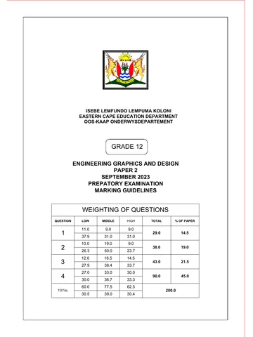
Engineering Graphics Design PAT GR 12 2022 Eng
Grade 12 Engineering Graphic And Design practical assessment task from the 2022 (English), 27 pages. Read online or get the free PDF download.
Engineering Graphic And Design · Grade 12 · 2022 · English. Practical assessment task, 27 pages. Read online or download the PDF.
- Subject
- Engineering Graphic And Design
- Grade
- Grade 12
- Language
- English
- Document type
- Practical assessment task
- Year
- 2022
- Curriculum
- CAPS
- Pages
- 27
- File size
- 927.5 KB
Loading document…
Loading document…
1 of 27
Document textSearch extracted text and jump to a page.
Downloaded from hlayiso.com
Engineering Graphics and Design 2 DBE/PAT 2022
NSC
TABLE OF CONTENTS
1. INTRODUCTION 3
SECTION A (TEACHER GUIDELINES) 4
2. STRUCTURE OF THE EGD PAT 4
3. INSTRUCTIONS FOR THE ADMINISTRATION OF THE PAT 5
4. ASSESSMENT AND MODERATION OF THE PAT 6
4.1 Assessment 6
4.2 Moderation 7
5. CONCLUSION 8
SECTION B (LEARNER TASKS) 9
6. PRACTICAL ASSESSMENT TASK 1 (PAT 1) 10
A civil design task 10
7. PRACTICAL ASSESSMENT TASK 2 (PAT 2) 17
A mechanical design task 17
8. ANNEXURE A: ASSESSMENT RUBRIC 24
9. SIMPLIFIED RUBRIC FOR ALLOCATION AND VERIFICATION OF MARKS 25
10. 2022: SUMMATIVE ASSESSMENT SHEET 26
11. DECLARATION OF AUTHENTICITY 27
Copyright reserved Please turn over
Downloaded from hlayiso.com
Engineering Graphics and Design 3 DBE/PAT 2022
NSC
1. INTRODUCTION
The 18 Curriculum and Assessment Policy Statement subjects which contain a practical
component all include a practical assessment task (PAT):
AGRICULTURE: Agricultural Management Practices, Agricultural Technology
ARTS: Dance Studies, Design, Dramatic Arts, Music, Visual Arts
SCIENCES: Computer Applications Technology, Information Technology,
Technical Sciences, Technical Mathematics
SERVICES: Consumer Studies, Hospitality Studies, Tourism
TECHNOLOGY: Engineering Graphics and Design, Civil Technology, Electrical
Technology, Mechanical Technology
A practical assessment task (PAT) is a compulsory component of the final promotion mark
for all candidates offering subjects that have a practical component and counts 25% (100
marks) of the end-of-year examination mark. The PAT is implemented across the first three
terms of the school year. This is broken down into different phases or a series of smaller
activities that make up the PAT. The PAT allows for learners to be assessed on a regular
basis during the school year and it also allows for the assessment of skills that cannot be
assessed in a written format, e.g. test or examination. It is therefore important that schools
ensure that all learners complete the practical assessment tasks within the stipulated period
to ensure that learners are resulted at the end of the school year. The planning and
execution of the PAT differs from subject to subject.
Copyright reserved Please turn over
Downloaded from hlayiso.com
Engineering Graphics and Design 4 DBE/PAT 2022
NSC
SECTION A (TEACHER GUIDELINES)
2. STRUCTURE OF THE PAT
The Engineering Graphics and Design (EGD) PAT is a compulsory national formal
assessment task that contributes 100 marks (25%) towards a learner's final NSC mark. It is
therefore regarded as a third NSC examination paper.
The purpose of the PAT is to assess topics, content and concepts, which are contained in
the CAPS, but not assessed in tests or examinations. These are:
The design process
The application of the design process
The quality and neatness of freehand, instrument and CAD drawings
With the inclusion of the research component as part of the design process, content and
concepts that are not included in the CAPS may be included in the PAT. The PAT is
therefore designed to develop a learner's ability to integrate and apply knowledge that is
taught and self-acquired, and to demonstrate attained levels of skills and competency.
The PAT gives the learner an opportunity to apply knowledge in a creative way through the
design process. The learner is also given an opportunity to complete the PAT in an
environment which is more conducive to the creative processes. This environment should
therefore provide the learner with easier access to, and a wider variety of, resource material
than would otherwise be available in a formal test or examination.
The PAT is divided into THREE PHASES:
PHASE 1: The design process
PHASE 2: Preparing working and pictorial drawings
PHASE 3: Creating the PAT file/portfolio
The three PHASES require that the learner demonstrates a clear understanding of, and is
able to apply, the design process. As part of the design process, the learner must be able to
do the following:
Analyse the given scenario and formulate a design brief that includes a list of
specifications, constraints and a management plan
Conduct relevant and usable research
Use the research in generating ideas/concepts/solutions, analytically and graphically,
using freehand drawings
Select a final solution that demonstrates a clear understanding of the design brief
Present the final solution as a set of working drawings and a pictorial (3D) drawing
Provide clear evidence of continuous self-evaluation during the development of the PAT
Create a PAT file/portfolio
PHASE 1 and PHASE 2 of the PAT have been designed to give the learner the opportunity
to demonstrate a level of competency and skill that has been attained in the following
drawing methods:
Freehand drawings, prepared using a pencil and grid/graph paper only
Instrument drawings, prepared in pencil and using drawing instruments
CAD drawings, prepared using a CAD program
TWO practical assessment tasks (PATs) are included in this document:
PAT 1 is a task in the context of civil technology, with an electrical component
PAT 2 is a task in the context of mechanical technology
With the guidance of the teacher, each learner must, select and complete ONE PAT only.
Copyright reserved Please turn over
Downloaded from hlayiso.com
Engineering Graphics and Design 5 DBE/PAT 2022
NSC
Elements that make up the PAT mark for Engineering Graphics and Design
ELEMENTS OF THE MARK FOR THE PRACTICAL ASSESSMENT TASK
The design process 25%
The correctness of the working and pictorial drawings 50%
The drawing methods (freehand, instrument and CAD) 25%
TOTAL 100%
3. INSTRUCTIONS FOR THE ADMINISTRATION OF THE PAT
The teacher must provide a copy of and mediate the entire SECTION B (pages 9 to 27)
of this 2022 PAT document to all Grade 12 learners no later than Week 5 of Term 1.
Each phase must be completed and assessed prior to commencement of phase moderation
in Terms 2 and 3, and provincial moderation in Terms 3 and 4.
The phases of the PAT must therefore be completed within the following timeframes:
PHASE 1: Design process (completed before the commencement of Term 2)
PHASE 2: Presentation drawings (completed before the commencement of Term 3)
PHASE 3: Completion of ALL presentation tasks and creation of file/portfolio
(completed in Term 3 before the commencement of the final provincial moderation,
or at the latest, before the commencement of the preparatory examinations).
Although the PHASES could be completed either cyclically or during block times, as
indicated in the CAPS, it is recommended that one entire day per term be allocated to
each PHASE (e.g. as an extra paper during the June examinations).
Teaching time allocated for the preparation and completion of all three PHASES of the PAT
may not exceed 16 hours. However, additional non-teaching time may also be allocated
for the completion of the PAT at the school, but the total time allocated for the completion
of all the PHASES of the PAT should NOT exceed 20 hours.
To ensure that the PAT is completed within the stipulated timeframes, it is essential that the
teacher prepares and communicates a management plan/pacesetter with target dates. This
will help learners monitor their own progress, and for the teacher to implement intervention
programmes.
NOTE:
To ensure the integrity of the PAT as a 'third NSC examination paper', the following
additional instructions must be adhered to. Non-compliance with any of these and
afore-mentioned instructions will be deemed a serious irregularity.
It is the responsibility of the teacher to ensure that each learner's PAT is of an
appropriate Grade 12 level and complexity.
ALL presentation requirements of the selected PAT must be adhered to strictly.
Except for the required research component, ALL the presentation requirements of
the PAT must be completed at school under the supervision of the teacher.
Explanatory examples, e.g. graphical illustration, best practices from previous years'
PATs, etc., may ONLY be presented to the learners during the initial mediation of
the PAT. As the explanatory examples may not be given to the learners or left for them
to view after the initial mediation, learners must be encouraged to take notes during the
initial mediation, but may NOT take any photographs or videos.
Although the sharing of knowledge and ideas between learners is permissible, no
presentation may be shared or copied as the entire PAT must be completed
individually. ALL the presentations, including the front page, table of contents,
management plan etc., must be the learner's own original work.
Copyright reserved Please turn over
Downloaded from hlayiso.com
Engineering Graphics and Design 6 DBE/PAT 2022
NSC
Except for clean A4 and A3 drawing sheets and grid/graph paper, NO templates, pre-
prepared pages/drawing sheets, redrawn examples of the site plan etc., may be
provided to the learners in any form or format.
NO examples of possible or suggested solutions of any component of the PAT may
be provided to, or procured for, the learners in any form or format. This includes,
but is not limited to, examples developed by any individual, group, department,
institution, organisation or business.
ALL learners must be encouraged to work on their own, with minimal intervention.
Developmental feedback and guidance may ONLY be given on presentations or a
PHASE that has already been prepared/completed, or when the learner requests it.
The DECLARATIONS OF AUTHENTICITY, as set out on page 27 of this document,
must be completed and signed by learner and the teacher prior to the final assessment.
The SUMMATIVE ASSESSMENT SHEET, as set out on page 26 of this document,
must be completed in full for each learner following the final assessment of the PAT.
The teacher must ensure that ONLY the completed SUMMATIVE ASSESSMENT
SHEET, DECLARATION OF AUTHENTICITY and relevant CHECKLIST are included
after the table of contents in each learners completed PAT file/portfolios.
4. ASSESSMENT AND MODERATION OF THE PAT
4.1 Assessment
Assessment of the PAT must be done according to the included and relevant
ASSESSMENT CRITERIA AND CHECKLIST.
As frequent developmental feedback is needed to determine and provide guidance and
support to the learner, as well as to ensure that they are on the right track ('assessment
for learning'), both formal and informal assessment must be conducted throughout the
development of the PAT. Informal assessment may be conducted by either a peer or
by the teacher.
The teacher must conduct ALL formal assessment and record the results on the
official mark sheets. The marks of each learner must also be indicated on the official
SUMMATIVE ASSESSMENT SHEET (see page 26), which must be included in the
learner's PAT file/portfolios.
The final formal assessment must be completed before commencement of final
provincial moderation or, at the latest, before the commencement of the
preparatory examinations in the Term 3.
Once the PATs have been assessed and moderated, the teacher/school must retain
ALL the PATs for external moderation. ALL the PATs must also be retained at school
for a period of time as stipulated by the provincial departments of education.
Clarification of level descriptors and the verification of marks:
1-mark level descriptor:
This level descriptor is used for elementary/basic presentation requirements
and/or drawing features, and must be applied as follows:
o '0' (zero) must be allocated for the requirement not met, or if the presentation is
incorrect.
o 1 mark may only be allocated if the requirement has been met fully and the
presentation is correct.
Copyright reserved Please turn over
Downloaded from hlayiso.com
Engineering Graphics and Design 7 DBE/PAT 2022
NSC
2-mark level descriptor:
o '0' (zero) must be allocated if the requirement has not been included/shown,
or if the presentation of the requirement shows less than 30% evidence of
knowledge, or when the requirement is very poor.
o 1 mark must be allocated if the presentation of the requirement shows at least
30% or more evidence of knowledge, or the requirement is NOT complete or
NOT completely correct, NOT compliant and/or clear, i.e. average.
o 2 marks may only be allocated if the presentation of the requirement shows at
least 80% or more evidence of knowledge, and the requirement is more
than 80% complete, correct/compliant and clear, i.e. very good.
7-mark level descriptor
Refer to the 7-mark rubric on page 45 of the CAPS document for the level
descriptors. This implies that a '7' can only be allocated if the presentation
requirement(s) is 100% correct/compliant, i.e. outstanding and error-free.
Verification of ALL final marks out of 10:
Each final mark out of 10 must be verified according to the descriptors contained in
the rubric on page 24 of this document. This implies that a '10' can only be
allocated if the presentation requirement/s is 100% correct/compliant, i.e. perfect
and error-free.
Rounding-off of marks:
Each mark out of 10 must be rounded off before being captured on the
SUMMATIVE ASSESSMENT SHEET (see page 26) and the recording/mark sheet.
4.2 Moderation
Moderation of the PAT must be done according to the included relevant
ASSESSMENT CRITERIA AND CHECKLISTS.
As monitoring and/or moderation of the PAT can take place at any stage during the
development of the PAT. ALL completed presentation requirements of ALL the
PATs must always be available at the school.
To facilitate intervention programmes and processes, the following school-based and
cluster/district moderation must be done during Terms 2 and 3:
Phase 1: Design process (beginning of Term 2 before the commencement of
PHASE 2, or at the latest before the May/June examinations)
Phase 2: Presentation drawings (beginning of Term 3 before the commencement
of PHASE 3)
Final provincial moderation must be concluded before the commencement of DBE
and/or Umalusi moderation, or at the latest by the end of Week 3 of Term 4.
To assist the moderator with the moderation process, the teacher must supply a
complete set of updated mark sheets and merit lists.
At the beginning of the moderation process the moderator must randomly select 10%,
with a minimum of THREE and a maximum of SIX PAT files/portfolios. The selected
PATs must be:
▪ No. 1 – a high/highest mark; ▪ No. 2 – an average/middle mark; ▪ No. 3 – a low mark;
▪ No. 4 – an average/middle mark; ▪ No. 5 – a high mark; ▪ No. 6 – a low mark.
If the selected PATs do not provide a consistent result, THREE additional PATs, i.e. a
high-, an average/middle- and a low-mark PAT, must be selected and moderated to
obtain more consistent results.
Copyright reserved Please turn over
Downloaded from hlayiso.com
Engineering Graphics and Design 8 DBE/PAT 2022
NSC
If a school has more than ONE Grade 12 EGD teacher, THREE PATs, i.e. a high-, an
average/middle- and a low-mark PAT, must be selected from each teacher.
During the moderation process learners may be called upon to explain the functions
and principles of operating a CAD program, and to demonstrate drawing skills through
performing capability tasks.
NOTE:
A tolerance range of ONLY 5% is permissible between the average assessed mark
and the average moderated mark of the PATs selected for moderation. Only once
moderation has been completed must the more than 5% difference between the
average marks of the moderated PATs be applied to the remainder of the PAT's.
5. CONCLUSION
On completion of the practical assessment task, learners should be able to demonstrate
their understanding of the design process, their enhanced knowledge, skills, values and
reasoning abilities as well as establish connections to life outside the classroom and
address real-world challenges. The PAT furthermore develops learners' life skills and
provides opportunities for learners to engage in their own learning.
Copyright reserved Please turn over
Downloaded from hlayiso.com
Engineering Graphics and Design 9 DBE/PAT 2022
NSC
SECTION B (LEARNER TASKS)
General information and instructions:
The PAT is a compulsory national formal assessment task that contributes 100 marks
(25%) towards your final National Senior Certificate (NSC) mark.
This document contains the following TWO PAT scenarios:
o PAT 1: A civil design task, with an electrical component
o PAT 2: A mechanical design task
You, the learner, with the guidance of your teacher, must select and complete ONE of the
PAT tasks contained in this document.
ALL the presentation requirements of the selected PAT must be strictly adhered to and,
with the exception of the research component, be completed at school, under the
supervision of your teacher.
Although the sharing of knowledge and ideas is permissible, no presentations may be
shared or copied. The entire PAT must be completed individually and ALL the
presentations, including the front page, table of contents, management plan etc., must be
your own original work.
The PAT must be completed in phases and within the given time frames of your teacher's
pacesetter/management plan.
ALL freehand drawings and instrument drawings must be prepared in pencil.
The PAT must be of an appropriate higher-order Grade 12 complexity.
The PAT will be assessed according to the relevant ASSESSMENT CRITERIA AND
CHECKLISTS, which are included in this PAT document.
The relevant ASSESSMENT CRITERIA AND CHECKLIST for the PAT (i.e. either pages 15
and 16 or pages 22 and 23) must be used to provide clear evidence of your own continuous
self-evaluation and the meeting of the deadlines during the development of the PAT.
Prior to the final submission of your complete PAT, you must complete and sign the
DECLARATION OF AUTHENTICITY, as set out on page 27 of this document.
ONLY the 2022 SUMMATIVE ASSESSMENT SHEET, your completed and signed
DECLARATION OF AUTHENTICITY, the completed 2022 CHECKLIST and ALL your
presentations must be included in the correct sequence in your PAT file/portfolio.
You are not permitted to use any of the photographs/pictures and/or websites contained in
this PAT document.
Untidy and messy work, as well as the late submission of presentation requirements, will be
penalised.
Copyright reserved Please turn over
Downloaded from hlayiso.com
Engineering Graphics and Design 10 DBE/PAT 2022
NSC
6. PRACTICAL ASSESSMENT TASK 1 (PAT 1)
A civil design project
Scenario
A non-governmental organisation (NGO), whose purpose it is to source funds to help
schools that need additional facilities, identified a school in your area that needs a new
building consisting of a media centre, a kitchen and toilet facilities. The NGO has decided to
broaden its mandate and is running a competition requiring design solutions for the building.
The design firm that you work for has decided to enter the competition and has tasked you
to come up with and submit a suggested design solution.
The brief for the competition states that the new building must be a freestanding 'L-shaped'
or a 'T-shaped' single-storey brick structure with a double-pitched hip and valley roof with a
corrugated iron finish.
The new building will forthwith simply be referred to as the building in this project.
To support the Read to Lead campaign, the media-centre section of the building must
consist of a small modern library, as well as a separate computer room with TEN built-in
computer stations. The entire media-centre section of the building must have a floor area of
at least 180 m², with only one entrance in the form of double aluminium and glass swing
doors. The library and the computer room must have a common glass-walled office of
approximately 15 m², from where all activities and movement in both the library and the
computer room can be monitored. The office must also be accessible from both the library
and the computer room. The media centre must have an 18 m² storeroom with no windows
and a roll-up door for security purposes. There must be a built-in issuing desk situated near
the entrance of the library to record the issuing and returning of books as well as ample built-
in bookshelves along all the walls The greater part of the library must be an open space for
additional freestanding bookshelves and magazine racks, as well as tables and chairs where
learners can sit and read books.
Adjacent to the media centre must be a kitchen with a total area of at least 70 m² where food
will be prepared for the school's feeding scheme. The kitchen must have sufficient work
surfaces for the preparation of food as well as two double sinks and space for two industrial
stoves and two industrial fridges. There must be a 4 m wide serving hatch with a roll-up door
in one of the outer walls. Inside the kitchen there must also be an 18 m² pantry, which must
be placed close to a 3 m wide delivery doorway with a roll-up door. The kitchen must have
one external door, and for safety purposes, an emergency exit door to the media centre.
The building must include separate male and female toilet facilities, which must cater for
learners in wheelchairs, and be accessible from the outside only. The female toilet facility
must have a hand-wash basin and two separate toilets, and the male toilet facility a hand-
wash basin, a separate toilet and a single wall-mounted urinal.
The building must include undercover walkways that run along the outside of the building,
linking the toilet facilities and the kitchen's serving hatch to the entrance of the media centre.
An undercover walkway must extend from the entrance of the media centre to the existing
school buildings. As the school caters for disabled learners, the undercover walkways must
be wide enough to allow two wheelchairs to pass comfortably.
There must be sufficient electrical lighting and switched socket outlets in all the rooms and
areas in the building. There should also be sufficient windows to let in as much natural light
as possible. All sewerage and waste-water from the building must be connected to the
existing sewerage lines on the school property. The entire building may not exceed 280 m².
Copyright reserved Please turn over
Downloaded from hlayiso.com
Engineering Graphics and Design 11 DBE/PAT 2022
NSC
Given: The site plan of the school
PHASE 1: PRESENTATION REQUIREMENTS
1. Analyse the given scenario and formulate a design brief in two paragraphs:
The first paragraph must, in your own words, give a brief background to the project,
as well as a detailed description of what has to be designed.
The second paragraph must, in your own words, give a clear overview of your role
in the project, as well as a description of the complete design process that you are
going to implement to complete this project (PAT).
From the scenario and your teacher's management plan, include the following as part
of the design brief:
A list of at least 20 of the given specifications.
A list of at least FIVE possible constraints. However, the specifications that you
have listed may not be repeated or reworded as possible constraints.
Your own management plan that specifies target dates for the completion of each
presentation requirement.
2. Conduct research on:
Designs and floor-plan layouts of small modern libraries and media centres
THREE examples of hip and valley roofs and THREE examples of covered
walkways
Designs and construction/drawing details of roll-up doors for serving hatches
Copyright reserved Please turn over
Downloaded from hlayiso.com
Engineering Graphics and Design 12 DBE/PAT 2022
NSC
NOTE:
The research must be usable and should therefore be in the form of graphic
material, i.e. of relevant pictures and/or illustrations for each topic.
Evidence of at least FIVE different examples of each research topic must be
included in the PAT file/portfolio, unless otherwise stated.
The research material should be aesthetically presented and may NOT exceed
FOUR A4 or TWO A3 pages per topic.
There must be clear evidence that the research has been used in your proposed
design solution.
Include a list of ALL references used (Bibliography).
3. Prepare neat detailed freehand drawings of the floor-plan layout of TWO possible
design solutions for the proposed new building. Each freehand drawing must show the
correct presentation of ALL the building features, the permanent fixtures, the roofline,
the undercover walkway, as well as the primary dimensions and labels. The calculations
for the total floor area of the media centre and the total area of the entire building,
excluding the walkways, must be clearly shown in a table on the drawing sheet of each
freehand drawing.
NOTE:
Grid/Graph paper must be used to assist with the preparation of the freehand
drawings so that ALL features and fixtures are drawn to proportion. The grid/graph
paper used must be included in the PAT file/portfolio.
ALL aspects of the freehand drawing, including dimensions, tables, labels and
possible information blocks must be prepared using a pencil ONLY. The use of
any other drawing instruments, e.g. a ruler and compass, will be penalised.
NO borders or title panels are required for the drawing sheets, and electrical fittings
and waste-water disposal systems are NOT required on the freehand drawings.
The drawings may be prepared on either A4 or A3 drawing sheets and must
comply with the guidelines and graphical symbols contained in the SANS 10143.
The drawings must provide clear evidence that a high level of competency has
been attained in the freehand drawing method.
4. Select the best solution that demonstrates an in-depth understanding of the scenario
within the context of the design brief, specifications and constraints.
On a separate page, compare and evaluate the TWO freehand solutions by:
Creating a table with a minimum of SIX descriptive criteria
Creating and applying a simple rating scale to score each solution against each
criterion
Justifying each score by describing the positive and/or negative aspects of each
solution against each criterion
Complete the process by writing a comprehensive summary giving reasons for your
selected freehand solution. The summary must also include whether any late changes
were made to the selected freehand solution, or not. If there were, they must be clearly
described.
Copyright reserved Please turn over
Downloaded from hlayiso.com
Engineering Graphics and Design 13 DBE/PAT 2022
NSC
PHASE 2: PRESENTATION REQUIREMENTS
5. Present the selected solution as a set of working drawings and a pictorial drawing
(5.1, 5.2 and 5.3) that meet the following criteria:
All the working drawings must be prepared on appropriately sized drawing sheets,
set up with correct borders. ONLY ONE of the drawing sheets must be set up with
a complete civil title panel.
The drawings must provide clear evidence that a high level of competency has
been attained in the following TWO drawing methods:
o Instrument drawing
o CAD (computer-aided drawing/design)
NOTE:
o ONE entire working drawing (i.e. 5.1.1, 5.1.2 and 5.1.3 or 5.2) must be prepared
using drawing instruments and the other using a CAD program.
o The perspective drawing (5.3) may be prepared using either drawing
instruments or a CAD program.
o Schools that do not have CAD facilities must prepare all the required working
drawings and pictorial drawing (i.e. 5.1, 5.2 and 5.3) using a pencil and drawing
instruments.
The title panel and ALL aspects of all drawings must comply with the guidelines,
drawing symbols, graphical symbols and representations contained in the
SANS 10143.
5.1 Draw detailed LAYOUT DRAWINGS of the selected freehand solution of the
complete building, including a 3 m section of the extended undercover walkway to
the existing buildings, clearly showing all the required building features.
The layout drawings must show the following orthographic views:
5.1.1 The complete FLOOR PLAN, drawn to a suitable scale, but preferably not
smaller than scale of 1 : 75.
5.1.2 TWO ELEVATIONS, drawn to the same scale as the floor plan, with one
view showing the front entrance to the media centre, and the other
showing a side view. Both views must include detail of the undercover
walkways.
5.1.3 A DETAILED SECTION(S), drawn to scale 1 : 20, showing all the detail
from the foundation to the roof, on a cutting plane that passes through the
serving hatch, and either an internal door, an external door or a window.
NOTE: Use break lines to divide the detailed section into TWO or more
parts, each representing a width of ±1½ m.
Include the following on ALL relevant views:
ALL exterior features, including door and window detail.
NOTE: ALL window and door frames must be shown in the TWO elevations
The roof detail, including all rainwater items and roof lines
ALL permanent fixtures
ALL electrical fittings and the wiring detail
Waste-water disposal systems (sewerage)
Titles, labels and notes
Scales used
Detailed dimensioning
Cutting plane(s)
All hatching detail
North point
Copyright reserved Please turn over
Downloaded from hlayiso.com
Engineering Graphics and Design 14 DBE/PAT 2022
NSC
5.2 Draw, to a suitable scale, a complete detailed SITE PLAN of STAND 61.
Include the following:
ALL the given general site details and features of STAND 61
Existing school buildings, driveways, parking areas and sports field
The proposed new building and complete walkway
ALL sewerage detail
Dimensions, including the reference/setting-out dimension and corner
heights
Scale
North point
5.3 Draw a detailed 'bird's-eye view' TWO-POINT PERSPECTIVE DRAWING of
the building that shows the entrance to the media centre and the 3-metre section
of the undercover walkway to the existing buildings. The horizon line (HL) must be
at the same height as (i.e. in line with) the top of the roof of the building.
Evidence of the following must be included:
All views/drawings used to produce the perspective drawing
The construction method used to produce the perspective drawing
NOTE: Use a copy of the perspective drawing, which may contain artistic
features, as the picture for the cover page of your PAT file/portfolio.
PHASE 3: PRESENTATION REQUIREMENTS
Create a PAT file/portfolio containing the following in the given sequence:
A complete cover page
An table of contents
The 2022 SUMMATIVE ASSESSMENT SHEET (see page 26)
The completed DECLARATION OF AUTHENTICITY (see page 27)
Include the following PHASE 1 and PHASE 2 presentation requirements in the PAT
file/portfolio after the DECLARATION OF AUTHENTICITY:
1. ALL the design brief requirements
2. Evidence of ALL the resource material used for the required research
3. The TWO freehand drawings of the possible design solutions
4. ALL the evidence of the selection of the best solution
5. ALL the required working drawings (5.1 and 5.2) and the perspective drawing (5.3)
6. The 'ASSESSMENT CRITERIA AND CHECKLIST FOR THE 2022 CIVIL PAT' (see
pages 15 and 16), which must provide clear evidence of your own continuous self-
evaluation and the meeting of the deadlines during the development of the PAT.
NOTE:
Include the following on each page:
Clear numbering according to the numbers of the presentation requirements
Your (the learner's) name
The date of completion and submission
Assessment criteria and checklist for the 2022 Civil PAT
The SUMMATIVE ASSESSMENT SHEET on page 26 of the PAT document must be
used to indicate the final totals out of 10 for each assessment criterion.
The contribution of each aspect of the PAT is as follows:
o The design process, i.e. presentation requirements numbers 1, 2, 3, 4, 6 and 7, will
contribute 25 marks out of 100
o The working drawings and the pictorial drawing, i.e. presentation requirement
number 5, will contribute 50 marks out of 100
o Drawing methods, drawing skills and presentation, which should be assessed
according to ANNEXURE A, will contribute 25 marks out of 100.
Copyright reserved Please turn over
Downloaded from hlayiso.com
Engineering Graphics and Design 15 DBE/PAT 2022
NSC
ASSESSMENT CRITERIA AND CHECKLIST FOR THE 2022 EGD CIVIL PAT
1-mark level 0 Requirement not met or presented incorrectly
Comments
Maximum
Checked
descriptive 1 Requirement has been met and/or presented correctly
0 Requirement not met, or less than 30% evidence of knowledge shown (very poor)
mark
2-mark level
1 Requirement included and at least 30%+ evidence of knowledge shown (avg.)
descriptive
2 Presentation shows at least 80% or more evidence of knowledge (very good)
1. Design Brief
1.1 1st paragraph: background and comprehensive description of what to design 2
1.2 2nd paragraph: your role and description of the design process you are going to use 2
1.3 A list of at least 20 given specifications in the scenario 2
1.4 A list of at least FIVE possible constraints in the scenario 2
1.5 A management plan with possible target dates for ALL the presentation requirements 2
TOTAL 10
2. Research (This should be restricted to a maximum of FOUR A4 or TWO A3 pages per topic.)
Relevant and 2.1 Designs and floor plan layouts of small modern libraries and media centre 2
usable 2.2 THREE hip and valley roofs, and THREE covered walkways 2
research on: 2.3 Designs and construction/drawing detail of roll-up doors for a serving hatch 2
Clear evidence that the research has been used in your proposed design solutions 2
A list of ALL references (Bibliography) 2
TOTAL 10
3. Freehand drawings of TWO possible design solutions Final mark for each solution
Assess The new building showing all the rooms/areas and the walkways 2
each Correct presentation of building features (roofline, walls, doors etc.) 2
freehand Solution 1 10
ALL fixtures (toilets, hand-wash basins, built-in counters, etc.) 2
solution Correct presentation of all fixtures according to SANS 10143 2
as Relative size/proportion of ALL features to each other 2
follows: Primary labels (2) + primary dimensions (2) (2 + 2 = 4) 4
Solution 2 10
2 x area calculations shown and within the specifications (2 + 2 = 4) 4
Design: functionality and effective utilisation of space 2
Subtotal = 20 ÷ 2 = TOTAL 20
4. Selecting the best freehand solution (This must be a separate presentation.)
A table created for the selection process 2
A minimum of SIX descriptive criteria to compare and evaluate 2
A simple rating scale created, and used to score each solution against each criterion 2
Each score justified by describing the positive and/or negative aspects against each criterion 2
Comprehensive summary with reasons for selected solution (including possible late changes) 2
TOTAL 10
5. Layout drawings and a pictorial drawing of selected solution
Drawing sheet preparation
Appropriately sized drawing sheets used 1
Correct borders on all the drawing sheets of all the working drawings 2
Complete SANS 10143 compliant civil title panel on ONE of working drawing's drawing sheet 7
NOTE: Use the 7-mark simplified rubric on page 45 of the CAPS. TOTAL 10
5.1 Detailed layout drawings of the proposed new building and covered walkway
5.1.1 FLOOR PLAN showing:
Correlation with selected freehand solution and selection process summary 2
ALL internal and external walls, walkways and rooflines 2
ALL doors and windows 2
ALL permanent fixtures including bookshelves and computer stations 2
ALL electrical fittings and the wiring detail 2
Waste-water disposal systems (sewerage) 2
Title, labels and notes (2) + Detailed dimensioning (2) (2 + 2 = 4) 4
Hatching detail (1) + Cutting plane (1) (1 + 1 = 2) 2
Suitable scale selected and correctly indicated (1) + North point (1) (1 + 1 = 2) 2
Subtotal = 20 ÷ 2 = TOTAL 10
Copyright reserved Please turn over
Downloaded from hlayiso.com
Engineering Graphics and Design 16 DBE/PAT 2022
NSC
ASSESSMENT CRITERIA AND CHECKLIST FOR THE 2022 EGD CIVIL PAT
5.1.2 TWO ELEVATIONS, that show the front entrance and a side view of the building
Prescribed views, i.e. front entrance to media centre and a side view, shown 1
External walls and features, incl. detail of the 3 m section of walkway to the existing
2
buildings
Door and window detail, including the door and window frames 2
Hip and valley roof detail, including rainwater items 2
Waste-water disposal system (sewerage) 2
Elevations drawn to same scale as the floor plan 1
TOTAL 10
5.1.3 DETAILED SECTION(S)
Section(s) correct according to the indicated cutting plane(s) 1
Foundation, slab and wall detail 2
Serving hatch and roller door detail
Internal/External door or window detail 2
Roof detail 2
Labels and notes 2
Detailed dimensioning 2
ALL hatching detail 2
Scale 1 : 20 used and indicated correctly (1) + Break lines (1) 2
(1 = 1; 2 = 1; 3 = 2; 4 = 3; 5 = 3; 6 = 4; 7 = 5; 8 = 5; 9 = 6; 10 = 7; 11 = 7; 12 = 8; 13 = 9; 14 = 9; 15 = 10) Subtotal = 15 ÷ 1,5 = TOTAL 10
5.2 Detailed SITE PLAN
Site plan correctly drawn with ALL the given site features 2
Complete proposed new building and complete walkway to existing buildings 2
ALL sewerage detail 2
Dimensions, including the setting-out dimensions and corner heights 2
Suitable scale selected and indicated correctly 1
North point 1
TOTAL 10
5.3 TWO-POINT PERSPECTIVE DRAWING showing the entrance to the media centre and the 3 m section of walkway
Evidence of the views, as well as construction and projections used to prepare the drawing 1
Correct orientation of the building with the HL at the same height as the top of roof 2
Detail and correctness of the perspective drawing 7
NOTE: Use the 7-mark simplified rubric on page 45 of the CAPS. TOTAL 10
6. Continuous self-evaluation and the meeting of deadlines
Completed checklist as evidence of continuous self-assessment (mark out of 10 ÷ 2) 5
Meeting ALL the deadlines (mark out of 10 ÷ 2) 5
TOTAL 10
7. Presentation of the complete PAT file/portfolio
Complete cover page with a copy of the perspective drawing 1
Table of contents 1
Summative assessment sheet and declaration 1
Correct sequencing of ALL presentation requirements 1
Name and numbering on the presentation requirements 1
Final presentation of the portfolio, e.g. binding, general appearance, etc. (mark out of 10 ÷ 2) 5
TOTAL 10
Assessment of drawing methods, drawing skills and presentation
a. Freehand drawings
Freehand drawing methods and skills (See ANNEXURE A on page 23)
NOTE: • No evidence of grid/graph paper used = max. 7 marks, even if drawn excellently 10
• Not drawn in freehand = 0 marks, & some evidence of instruments used = max. 5 marks
Neatness (2) + correct line types used (2) + line consistency (2) + printing (2) + dimensioning (2)
10
(Also see ANNEXURE A on page 23)
b. Instrument drawings
Use of drawing instruments, drawing methods and skills (See ANNEXURE A on page 23) 10
Neatness (2) + correct line types used (2) + line consistency (2) + printing (2) + dimensioning (2)
10
(Also see ANNEXURE A on page 23)
c. CAD drawings
Competence displayed in using a CAD program (See ANNEXURE A on page 23) 10
Layout and correctness of the drawings presentation (See ANNEXURE A on page 23) 10
Copyright reserved Please turn over
Downloaded from hlayiso.com
Engineering Graphics and Design 17 DBE/PAT 2022
NSC
7. PRACTICAL ASSESSMENT TASK 2 (PAT 2)
A mechanical design project
Scenario
During the Covid-19 pandemic we have all become accustomed to various types of sanitiser
dispensers that are used wherever we go. A mechanical design firm that specialises in
improving the design and function of mechanically operated devices is currently working on
design solutions to improve PEDESTAL-TYPE FOOT-OPERATED HAND SANITISER
DISPENSERS that incorporates mechanical components and mechanisms.
Examples of some of these pedestal-type foot-operated sanitiser dispensers are shown
below.
[Source: PRICEPULSE] [Source: www.archiexpo.com] [Source: scottguardusa.com]
As a design consultant for the mechanical design firm, you have been tasked with
investigating and analysing the design features of existing pedestal-type foot-operated
sanitiser dispensers and to come up with an improvement(s) that could be, but is not
limited to, one or more of the following:
Improved efficiency
To strengthen its design
Modify its design
Your investigation, analysis and solution require the following stages:
The FIRST stage involves finding or selecting a suitable pedestal type foot operated
sanitiser dispenser. The dispenser must be a mechanically-operated device that
incorporates a mechanical mechanism(s). The pedestal-type foot-operated sanitiser
dispensers that you have selected will forthwith be referred to as the selected
dispenser in this project (PAT).
NOTE: You are NOT required to purchase a dispenser. The selected dispenser should
therefore be one that is readily available to you.
The SECOND stage involves the dismantling of the selected dispenser so that all the
individual components/parts and mechanical mechanism(s) are revealed and can be
investigated, measured and photographed.
The THIRD stage requires the identification of ONE of the main moving mechanical
components/parts, or a combination of moving mechanical components/parts of the
selected dispenser, which could be improved, strengthened or modified in some way.
This will necessitate the application of the design process, as stipulated below in the
presentation requirements.
Copyright reserved Please turn over
Downloaded from hlayiso.com
Engineering Graphics and Design 18 DBE/PAT 2022
NSC
Requirements and specifications for the selected dispenser:
Each learner must have his/her own selected dispenser for the PAT.
Your own selected dispenser must be submitted as part of your PAT presentation.
If the selected dispenser is still being used, then photographs must be taken of the
entire dispenser, as well as ALL the different components/parts. A neat presentation
of the photographs must then be prepared, and submitted as part of the design
brief in your PAT file/portfolio.
The selected dispenser must be a mechanically-operated device that incorporates
a mechanical mechanism(s).
Digital or electronic dispensers may NOT be used.
Your teacher must approve your selected dispenser. This is to ensure that it meets the
requirements and that a PAT of an appropriate higher-order Grade 12 complexity can
be produced.
PHASE 1: PRESENTATION REQUIREMENTS
1. Analyse the given scenario and formulate a design brief in two paragraphs:
The first paragraph must, in your own words, give a brief background to the project,
as well as a detailed description of what has to be designed.
The second paragraph must, in your own words, give a clear overview of your role
in the project, as well as a description of the complete design process that you are
going to implement to complete this project (PAT).
From the given scenario and your teacher's management plan, include the following
as part of the design brief:
Your own list of ALL the specifications of your selected dispenser
Your own list of at least THREE constraints of your selected dispenser
Your own management plan, which specifies target dates for the completion of
each presentation requirement
2. Conduct research on:
The material used for each individual component/part of your selected dispenser
The specific design features and/or function/purpose of each individual component/
part of your selected dispenser
The design, components/parts and mechanical mechanism(s) of at least ONE other
pedestal-type foot-operated sanitiser dispenser that is similar to your selected
dispenser
NOTE:
The research must be relevant and should therefore be in the form of graphic
material, i.e. pictures and illustrations,
ALL the required research material must be included in the PAT portfolio.
The presentation of the research material must be aesthetically presented and may
not exceed FOUR A4 or TWO A3 pages per topic.
The first two research requirements will be primarily hands-on investigative
research, which must be presented using a comprehensive set of detailed
photographs taken during the second stage. Include labels and/or notes indicating
the material and the function (purpose) of each individual part/component.
The evidence of the ONE other similar dispenser may be in the form of a
comprehensive set of pictures, illustrations and/or photographs, together with
explanatory labels and notes.
There must be clear evidence that the research was used in your design solution.
Include a list of ALL references used (Bibliography).
Copyright reserved Please turn over
Downloaded from hlayiso.com
Engineering Graphics and Design 19 DBE/PAT 2022
NSC
3. Prepare TWO sets of neat, detailed freehand drawings of TWO possible solutions of
the proposed improvement, strengthening or modification of the identified main
component(s)/parts of your selected dispenser.
Each set of freehand drawings must consist of relevant orthographic views and an
isometric drawing(s) that include dimensions, labels and explanatory notes, as well as
the correct presentation of ALL the features. Include a short explanation of the possible
improvement, strengthening or modification.
NOTE:
Grid/Graph paper must be used to assist in preparing the freehand drawings so
that ALL features and fixtures are drawn to proportion. The grid/graph paper used
must be included in the PAT file/portfolio as evidence.
ALL aspects of the freehand drawing, including dimensions, labels, tables and
possible information blocks must be prepared using a pencil ONLY. The use of
any other drawing instruments, e.g. a ruler and compass, will be penalised.
NO borders or title blocks are required for the drawing sheets.
The drawings may be prepared on either A4 or A3 drawing sheets, and must
comply with the SANS 10111 Guidelines.
These drawings must provide clear evidence that a high level of competency has
been attained in the freehand drawing method.
4. Select the best solution, which demonstrates an in-depth understanding of the
scenario within the context of the design brief.
On a separate page, compare and evaluate the TWO freehand solutions by:
Creating a table with a minimum of FOUR descriptive criteria
Creating and applying a simple rating scale to score each solution against each
criterion
Justifying each score by describing the positive and/or negative aspects of each
solution against each criterion.
Complete the process by writing a comprehensive summary giving reasons for your
selected freehand solution. The summary must also include whether there are any late
changes made to the selected freehand solution, or not. If there are, they must be
clearly described.
PHASE 2: PRESENTATION REQUIREMENTS
5. Present your selected dispenser, and the selected improvement/strengthening/
modification as a set of working drawings and a pictorial drawing (5.1, 5.2 and 5.3) that
meet the following criteria:
All the working drawings must be prepared on appropriately sized drawing sheets,
set up with correct borders. ONLY the first drawing sheet (i.e. for 5.1) must be set
up with a complete mechanical title block as presented in the EGD NSC Paper 2
analytical questions.
The drawings must provide clear evidence that a high level of competency has
been attained in the following TWO drawing methods:
o Instrument drawing
o CAD (Computer-aided Drawing/Design)
NOTE:
o ONE entire working drawing (i.e. 5.1 or 5.2) must be prepared using drawing
instruments and the other using a CAD program.
o The isometric drawing (5.3) may be prepared using either drawing instruments
or a CAD program.
o Schools that do not have CAD facilities must prepare all the required drawings
(5.1, 5.2 and 5.3) by using drawing instruments
ALL aspects of all drawings must comply with the guidelines and conventional
representations contained in the SANS 10111.
Copyright reserved Please turn over
Downloaded from hlayiso.com
Engineering Graphics and Design 20 DBE/PAT 2022
NSC
5.1 Draw, to a suitable scale and in third-angle orthographic projection, an
ASSEMBLY DRAWING of your selected dispenser, clearly showing all the parts
before any improvements, strengthening or modifications have been affected.
NOTE: Use relevant S-breaks/break lines to shorten the height of your selected
dispenser in the assembly drawings, so that a larger scale can be used.
The assembly drawing must show the following FOUR views:
5.1.1 The FRONT VIEW
5.1.2 A second PRIMARY VIEW
5.1.3 Any other TWO SECONDARY VIEWS
NOTE: TWO of the views must be sectioned or contain types of sections.
Include the following:
Scale
Detailed dimensions
Labels and notes
Cutting plane(s)
ALL hatching detail
Projection symbol
5.2 Draw, to a suitable scale and in third-angle orthographic projection, a DETAILED
DRAWING of the identified component(s)/part(s) of your selected dispenser,
clearly showing the selected improvement/strengthening/modification.
The detailed drawing must show the following THREE views:
5.2.1 The FRONT VIEW
5.2.2 Any other TWO VIEWS
NOTE: ONE of the views must be sectioned or contain a type of section.
Include the following:
Comprehensive explanatory labels and notes
Relevant welding and/or machining symbols (if required)
Relevant tolerances (if required)
Scale(s)
Detailed dimensioning
Cutting plane(s)
ALL hatching detail
5.3 Draw, to a suitable scale, a detailed ISOMETRIC DRAWING of your selected
dispenser or of the improved, strengthened or modified component(s)/parts(s) that
is of an appropriate Grade 12 level of complexity.
NOTE:
Evidence of ALL auxiliary views and constructions used to produce the
drawing, must be clearly shown.
Use a copy of the isometric drawing, which may contain artistic features, as
the picture for the cover page of your PAT file/portfolio.
Copyright reserved Please turn over
Downloaded from hlayiso.com
Engineering Graphics and Design 21 DBE/PAT 2022
NSC
PHASE 3: PRESENTATION REQUIREMENTS
Create a PAT file/portfolio containing the following in the given sequence:
A complete cover page
An table of contents
The 2022 SUMMATIVE ASSESSMENT SHEET (see page 26)
The completed DECLARATION OF AUTHENTICITY (see page 27)
Include the following PHASE 1 and PHASE 2 presentation requirements in the PAT
file/portfolio after the DECLARATION OF AUTHENTICITY:
1. ALL the design brief requirements
2. Evidence of ALL the resource material used for the required research
3. The TWO freehand drawings of the possible design solutions
4. ALL the evidence of the selection of the best solution
5. ALL the required working drawings (5.1 and 5.2) and the isometric drawing (5.3)
6. The 'ASSESSMENT CRITERIA AND CHECKLIST FOR THE 2022 MECHANICAL
PAT' (see pages 21 and 22), which must provide clear evidence of your own
continuous self-evaluation and the meeting of the deadlines during the development of
the PAT.
NOTE:
Include the following on each page:
Clear numbering according to the numbers of the presentation requirements
Your (the learner's) name
The date of completion and submission
Assessment criteria and checklist for the 2022 EGD MECHANICAL PAT
The SUMMATIVE ASSESSMENT SHEET on page 26 of the PAT document must be
used to indicate the final totals out of 10 for each assessment criterion.
The contribution of each aspect of the PAT is as follows:
o The design process, i.e. presentation requirements numbers 1, 2, 3, 4, 6 and 7,
will contribute 25 marks out of 100
o The working drawings and the pictorial drawing, i.e. presentation requirement
number 5, will contribute 50 marks out of 100
o Drawing methods, drawing skills and presentation, which should be assessed
according to ANNEXURE A, will contribute 25 marks out of 100
Copyright reserved Please turn over
Downloaded from hlayiso.com
Engineering Graphics and Design 22 DBE/PAT 2022
NSC
ASSESSMENT CRITERIA AND CHECKLIST FOR THE 2022 EGD MECHANICAL PAT
1-mark level 0 Requirements not met or presented incorrectly
Comments
Maximum
Checked
descriptive 1 Requirements has been met and/or presented correctly
0 Requirements not met, or less than 30% evidence of knowledge shown (poor)
mark
2-mark level
1 Requirements included and at least 30% evidence of knowledge shown (avg.)
descriptive
2 Presentation shows at least 80% or more evidence of knowledge (very good)
1 Design Brief
1.1 1st paragraph: background and comprehensive description of what to design 2
1.2 2nd paragraph: your role and description of complete design process you are going to use 2
1.3 A list of ALL the specifications of your selected dispenser 2
1.4 A list of at least THREE constraints of your selected dispenser 2
1.5 A management plan with target dates for ALL the presentation requirements 2
TOTAL 10
2 Research (This should be restricted to a maximum of THREE A4 or TWO A3 pages per research topic)
Relevant 2.1 Materials used for each component of your selected dispenser 2
and usable 2.2 Design features/function/purpose of each component of your dispenser 2
research on: 2.3 The design, components, mechanisms, etc. of another similar dispenser 2
Clear evidence that the research has been used in your proposed design solutions 2
A list of ALL references (Bibliography) 2
TOTAL 10
3 Freehand drawings of TWO possible design solutions Final mark for each solution
Assess Relevant orthographic views of the component(s)/part(s) 2
each Isometric drawing of the component(s)/part(s) 2
Solution 1 10
freehand Correct presentation of ALL the components and features 1
solution The relative size of all features and fixtures 2
as Labels and explanatory notes 2
follows: Dimensioning 2
Solution 2 10
Description of improvement/modification/re-design 2
Functionality of improvement/modification/re-design 2
Subtotal = 15 ÷ 1,5 = TOTAL 15
(1 = 1; 2 = 1; 3 = 2; 4 = 3; 5 = 3; 6 = 4; 7 = 5; 8 = 5; 9 = 6; 10 = 7; 11 = 7; 12 = 8; 13 = 9; 14 = 9; 15 = 10)
4 Selecting the best freehand solution (This must be a separate presentation)
A table created for the selection process 2
A minimum of FOUR descriptive criteria to evaluate and compare 2
A simple rating scale created and used to score each solution against each criterion 2
Each score justified by describing the positive or negative aspects against each criterion 2
Comprehensive summary with reasons for selected solution (including possible late changes) 2
TOTAL 10
5 Working drawings and a pictorial drawing of your selected dispenser, and/or selected change(s)
Drawing sheet preparation
Appropriately sized drawing sheets 1
Borders on all the drawing sheets of working drawings 2
Appropriate and complete mechanical title block on the first working drawing (5.1) 7
NOTE: Use the 7-mark simplified rubric on page 45 of the CAPS. TOTAL 10
5.1 ASSEMBLY DRAWING of your selected dispenser, before any changes
5.1.1 FRONT VIEW before any changes
ALL the parts included and drawn correctly according to the actual selected dispenser 2
All hatching detail or, if not sectioned, ALL external features 2
ALL bolts and nuts and other fastening methods correct in ALL views 2
Labels and notes on ALL views 2
Projection symbol 1
Suitable scale selected and indicated correctly on ALL views 1
TOTAL 10
Copyright reserved Please turn over
Downloaded from hlayiso.com
Engineering Graphics and Design 23 DBE/PAT 2022
NSC
ASSESSMENT CRITERIA AND CHECKLIST FOR THE 2022 EGD MECHANICAL PAT
5.1.2 Second PRIMARY VIEW before any changes
ALL the parts included and drawn correctly according to the actual selected dispenser 2
All hatching detail or, if not sectioned, external features 2
Dimensions for ALL views 2
ALL centre lines on ALL views 2
ALL FOUR views drawn correctly in third-angle orthographic projection 2
TOTAL 10
5.1.3 TWO other SECONDARY VIEWS before any changes
Appropriate secondary views selected 2
ALL the parts included and drawn correctly according to the actual selected dispenser 2
All hatching detail or, if not sectioned, external features 2
TWO views sectioned or contain types of sections 2
Correct cutting planes for the TWO sectional views and/or types of sections 2
TOTAL 10
5.2 DETAILED DRAWING of the component(s), clearly showing the selected improvement/modification/redesign
Appropriate view selected as the FRONT VIEW, and is drawn correctly 2
TWO other relevant VIEWS selected, and drawn correctly 2
Improvement/Modification/Re-design correlates with selected freehand solution 2
Comprehensive explanatory labels and notes 2
Detailed dimensions 2
ONE view sectioned, or contain types of sections, and drawn correctly 2
Cutting plane(s) 1
ALL hatching detail 2
Relevant welding symbols and/or machining symbols and/or tolerances 2
Projection symbol 1
Suitable scale selected and indicated correctly 1
Drawing is in third-angle orthographic projection 1
Subtotal = 20 ÷ 2 = TOTAL 10
5.3 Detailed ISOMETRIC DRAWING
Suitable scale selected and indicated correctly 1
Evidence of ALL auxiliary views and constructions used for the drawing 2
Isometric drawing/answer 7
NOTE: Use the 7-mark simplified rubric on page 45 of the CAPS. TOTAL 10
6 Continuous self-evaluation and the meeting of deadlines
Checklist completed as evidence of continuous self-evaluation (mark out of 10 ÷ 2) 5
The meeting of ALL the deadlines during the development (mark out of 10 ÷ 2) 5
TOTAL 10
7 Presentation of the complete PAT file/portfolio
Cover page with a copy of the isometric drawing 1
Table of contents 1
Summative assessment sheet and declaration 1
Correct sequencing of ALL presentation requirements 1
Name and numbering on ALL the presentation requirements 1
General impression of file/portfolio, e.g. binding, appearance etc. (mark out of 10 ÷ 2) 5
TOTAL 10
Assessment of drawing methods, drawing skills and presentation
a Freehand drawings
Freehand drawing methods and skills (See ANNEXURE A on page 23)
NOTE: • No evidence of grid/graph paper used = max. 7 marks, even if drawn excellently 10
• Not drawn in freehand = 0 marks, & some evidence of instruments used = max. 5 marks
Neatness (2) + correct line types used (2) + line consistency (2) + printing (2) + dimensioning (2)
10
(Also see ANNEXURE A on page 23)
b Instrument drawings
Use of drawing instruments, drawing methods and skills (See ANNEXURE A on page 23) 10
Neatness (2) + correct line types used (2) + line consistency (2) + printing (2) + dimensioning (2)
10
(Also see ANNEXURE A on page 23)
c CAD drawings
Competence displayed in using a CAD program (See ANNEXURE A on page 23) 10
Layout and correctness of the drawings presentation (See ANNEXURE A on page 23) 10
Copyright reserved Please turn over
Engineering Graphics and Design
Downloaded from hlayiso.com 24 DBE/PAT 2022
NSC
8. ANNEXURE A: ASSESSMENT RUBRIC
ASSESSING DRAWING METHODS, DRAWING SKILLS AND PRESENTATION
LEVELS OF PERFORMANCE
MARK ALLOCATION 10 9 8 7 6 5 4 3 2 1 0
100% 99%–90% 89%–80% 79%–70% 69%–60% 59%–50% 49%–40% 39%–30% 29%–20% 19%–1% 0%
NOTE:
No evidence of grid/graph paper used = max. 7 marks, even if excellent
The drawings display drawing methods and skills are displayed! The drawings display poor
Not drawn in freehand, i.e. completely drawn with instruments, = 0 marks The drawings display very
correct freehand drawing drawing methods and skills
Freehand drawing
poor drawing methods
METHODS methods and skills. as If instruments were used for, or to assist with, some aspect = max. 5 marks, and there is little to no
and skills and no method
AND SKILLS well as the method used to evidence of the method used
even if excellent drawing methods and skills are displayed. was used to ensure correct
ensure good proportion which resulted in poor
The drawings display excellent drawing The drawings display satisfactory proportion.
and size proportion and size.
methods and skills and the method drawing methods and skills and the
used to ensure outstanding proportion method used to ensure satisfactory
and size. proportion and size.
Neatness (2) + correct line types used (2) + line quality/consistency (2) + compliant printing/writing (2) + compliant dimensioning (2)
Final drawing presentation is neat, and
Additional descriptors/guidelines:
the line types used, line
The drawings are untidy with
constancy/quality, printing and The drawings are very neat and all line The drawings are neat and line work/line The line work/line quality,
inconsistent line work/line
dimensioning is correct. work/line quality, printing and dimensioning quality, printing and dimensioning are printing and dimensioning are
quality, printing and
are outstanding and consistent. generally good and mostly consistent. unacceptable.
dimensioning.
The drawings display poor The drawings display an
The drawings display the The drawings display the correct use of The drawings display the correct use of
Instrument drawing
use of drawing instruments incorrect use of drawing
METHODS correct use of drawing drawing instruments and an drawing instruments and a satisfactory
and a poor and incorrect instruments with incorrect
AND SKILLS instruments, drawing outstanding application of drawing and mostly correct application of
application of drawing applications of drawing
methods and skills. methods and skills. drawing methods and skills.
methods and skills. methods and skills.
Neatness (2) + correct line types used (2) + line quality/consistency (2) + compliant printing/writing (2) + compliant dimensioning (2)
Final drawing presentation is neat, and
the line types used, line Additional descriptors/guidelines:
The drawings are untidy, and the
constancy/quality, printing and The drawings are very neat and all line The drawings are neat and the line work/line The line work/line quality,
line work/line quality, printing
dimensioning is correct. work/line quality, printing and dimensioning quality, printing and dimensioning are printing and dimensioning are
and dimensioning are
are outstanding and consistent. generally good and mostly consistent. unacceptable.
inconsistent.
METHODS The level of competence Displays a satisfactory level of skills, Displays a poor level of skills, Shows little to no skills,
Displays a high level of skills, knowledge
CAD drawing
AND displayed in using a knowledge and ability in using a CAD knowledge and ability in using knowledge or ability in using
and ability in using a CAD program
SKILLS CAD program program a CAD program a CAD program
The layout of the drawings is
The layout of the drawings is acceptable
Layout of the final drawing is correct and The layout of the drawings is correct and very poor and the line work, The layout, line work,
and the line work, printing and
the line work, printing and dimensioning the line work, printing and dimensioning printing and dimensioning are printing and dimensioning
dimensioning are mostly compliant and
are compliant and consistent are compliant and consistent. not compliant and are unacceptable.
consistent.
inconsistent.
Copyright reserved Please turn over
Downloaded from hlayiso.com
Engineering Graphics and Design 25 DBE/PAT 2022
NSC
9. SIMPLIFIED RUBRIC FOR ALLOCATION AND VERIFICATION OF MARKS
NOTE:
The final mark out of 10 of each assessment criterion, i.e. the overall level of
achievement according to the presentation requirement, must be verified according
to this rubric.
This rubric must also be used to allocate marks for all aspects of the assessment
criteria which require a mark out of 10.
VERIFICATION AND MARK ALLOCATION
GENERAL
DESCRIPTION FOR MARK ±% MARK
INDICATOR
ALL/MORE than ALL the REQUIREMENTS are met.
Error-free 100% 10
- PERFECT -
ALL (ALMOST ALL) the REQUIREMENTS are met.
Very few errors 90% + 9
- OUTSTANDING -
ALMOST ALL (MOST OF) the REQUIREMENTS
are met. Few errors 80% + 8
- VERY GOOD -
The REQUIREMENTS are met SUBSTANTIALLY.
70% + 7
- GOOD -
Some errors
The REQUIREMENTS are met ADEQUATELY.
60% + 6
- SATISFACTORY -
The REQUIREMENTS are met MODERATELY.
50% + 5
- ACCEPTABLE -
Many errors
ONLY SOME of the REQUIREMENTS are met.
40% + 4
- UNACCEPTABLE -
VERY FEW of the REQUIREMENTS are met. 30% +
Mostly wrong Only a few correct 3
- NOT ACHIEVED - features
29% and 2
The REQUIREMENTS are NOT met. Completely LESS
- VERY POOR - wrong Something done
incorrectly/
poorly 1
No work Nothing to
NOT DONE 0
handed in! mark!
Copyright reserved Please turn over
Downloaded from hlayiso.com
Engineering Graphics and Design 26 DBE/PAT 2022
NSC
10. PAT 2022: SUMMATIVE ASSESSMENT SHEET
PAT 2022
SUMMATIVE ASSESSMENT SHEET
NAME OF SCHOOL: ………………………………………………………………………………….… DISTRICT: …………………………………….
NAME OF LEARNER: ……………………………………………….………….. (NAME AND SURNAME)
NAME OF TEACHER: …………………………………........................……… (NAME AND SURNAME)
NAME OF MODERATOR: …………………………………..............………… (NAME AND SURNAME) DATE: ……………..………………………..….
PART A: Design Process PART B: Working and pictorial drawings Drawing competency and skill
CRITERIA MARK CRITERIA MARK CRITERIA MARK
A design brief All drawing sheets are appropriately set up with a The drawings display
demonstrating a clear border and an appropriate title block/panel. correct freehand drawing
METHOD
understanding of the scenario methods and skills and
Freehand drawing:
1 and the specifications, the method used to
View 1
Assess each view's accuracy and correctness according
constraints and a ensure proportion and
5.1.1
ANNEXURE A
PAT 1: Plan
management plan size.
PAT 2: Front view
Evidence of relevant and The final drawing presentation
2 usable research with the is neat and there is consistency
Orthographic drawings
inclusion of a bibliography View 2 of line work/line quality,
5.1.2 PAT 1: Elevations (x2) printing and dimensioning.
to the selected solution/device, the stipulated requirements and
PAT 2: 2nd main view
TWO detailed freehand
1st
Solution
The drawings display the
Instrument drawing:
View 3
drawings of possible METHOD
3 PAT 1: correct use of drawing
5.1.3 Detailed section(s) instruments, drawing
ANNEXURE A
drawing principals
2nd methods and skills.
solutions
PAT 2:
Solution Secondary views (x2)
PAT 1: The final drawing presentation
Site plan is neat and there is consistency
Selecting the best solution 5.2 PAT 2: of line work/line quality,
which demonstrates a clear Detailed drawing printing and dimensioning.
4 understanding of the
design brief
METHOD
Pictorial Drawing
The level of competence
The correct drawing
CAD drawing:
is displayed in using a
method and
ANNEXURE A
CAD program.
presentation of the
Clear evidence of 5.3 pictorial drawing. The layout of the final drawing is
evaluation and the meeting
6 of deadlines of all the
PAT 1: Perspective correct and the line work,
PAT 2: Isometric printing and dimensioning is
requirements
compliant and consistent.
The presentation of the
NO CAD drawings / 40
7 complete PAT portfolio
With CAD drawings / 60
CALCULATION
SUBTOTAL / 70 SUBTOTAL / 60 without CAD
X 0.63
CALCULATION
CALCULATION X 0.36 CALCULATION X 0.84 X 0.42
with CAD
Teacher's TOTAL Teacher's TOTAL Teacher's TOTAL
TOTAL: A / 25 TOTAL: B / 50 TOTAL: C / 25
Moderated TOTAL Moderated TOTAL Moderated TOTAL
TOTAL: A / 25 TOTAL: B / 50 TOTAL: C / 25
TEACHER: MODERATOR:
TEACHER'S TOTAL: A+B+C= / 100 Initial Initial
MODERATED TOTAL: A+B+C= / 100
Copyright reserved Please turn over
Downloaded from hlayiso.com
Engineering Graphics and Design 27 DBE/PAT 2022
NSC
11. DECLARATION OF AUTHENTICITY
DECLARATION OF AUTHENTICITY
To be submitted with each learner's practical assessment task portfolio
NAME OF THE SCHOOL: ……………………………………………………………………................
NAME OF LEARNER: ………………………………………………………........................................
(SURNAME AND INITIALS)
I hereby declare that all the contents of the practical assessment task (PAT) submitted by
myself for assessment is my own original work and has not been plagiarised, copied from
someone else or previously submitted for assessment.
_______________________ ___/___/2022
SIGNATURE OF LEARNER DATE (DD/MM/YYYY)
NAME OF TEACHER: ……………………………………………………………………….……………
(SURNAME AND INITIALS)
As far as I know, the above declaration by the candidate is true and I accept that the PAT
submitted is his/her own work.
_______________________ ___/___/2022
SIGNATURE OF TEACHER DATE (DD/MM/YYYY)
SCHOOL STAMP
Copyright reserved
Study this subject
Notes, quizzes and topic questions for Grade 12 Engineering Graphic And Design.
- Grade 12 Engineering Graphic And Design notes
CAPS revision notes with worked examples.
- Engineering Graphic And Design questions by topic
Past exam questions sorted by CAPS topic, with memos where available.
- All Grade 12 Engineering Graphic And Design past papers
Past papers by year, with memos where available.
- Grade 12 Practical assessment tasks
More Engineering Graphic And Design and other subjects in this collection.
Recommended for this subject
More papers and memos for this grade and subject.
Memorandum
Engineering Graphic And Design Grade 12 P1 2025 Memo
Memorandum
Engineering Graphic And Design Grade 12 P2 2025 Memo (Eng)
Memorandum
Engineering Graphic And Design Grade 12 P2 Gauteng June 2025 Memo
Memorandum
Engineering Graphic And Design Grade 12 P2 2024 Memo (Eng)
Question paper
Engineering Graphic And Design Grade 12 P1 2024 QP
Question paper
Engineering Graphic And Design Grade 12 P2 2024 QP
Related documents
Question paper
Engineering Graphic And Design Grade 12 P2 NSC June 2024 QP (Eng)
Memorandum
Engineering Graphic And Design Grade 12 P1 2022 Memo
Question paper
Engineering Graphic And Design Grade 12 P1 NSC November 2022 QP
Question paper
Engineering Graphic And Design Grade 12 P2 NSC November 2022 QP
Question paper
Engineering Graphic And Design Grade 12 P2 NSC November 2022 QP
Question paper
Engineering Graphic And Design Grade 12 P2 NSC November 2022 QP
More from Grade 12 Engineering Graphic And Design
Question paper
Engineering Graphic And Design Grade 12 P1 November 2024 NSC QP
Question paper
Engineering Graphic And Design Grade 12 P1 2024 QP
Question paper
Engineering Graphic And Design Grade 12 P2 2024 QP
Memorandum
Engineering Graphic And Design Grade 12 P1 2023 Memo
Question paper
Engineering Graphic And Design Grade 12 P2 2023 QP
Question paper