
Downloaded from hlayiso.com
NATIONAL SENIOR CERTIFICATE EXAMINATION
NOVEMBER 2017
MECHANICAL TECHNOLOGY
MARKING GUIDELINES
Time: 3 hours 200 marks
These marking guidelines are prepared for use by examiners and sub-examiners,
all of whom are required to attend a standardisation meeting to ensure that the
guidelines are consistently interpreted and applied in the marking of candidates'
scripts.
The IEB will not enter into any discussions or correspondence about any marking
guidelines. It is acknowledged that there may be different views about some
matters of emphasis or detail in the guidelines. It is also recognised that,
without the benefit of attendance at a standardisation meeting, there may be
different interpretations of the application of the marking guidelines.
IEB Copyright © 2017 PLEASE TURN OVER
Skip to contentMemorandum 

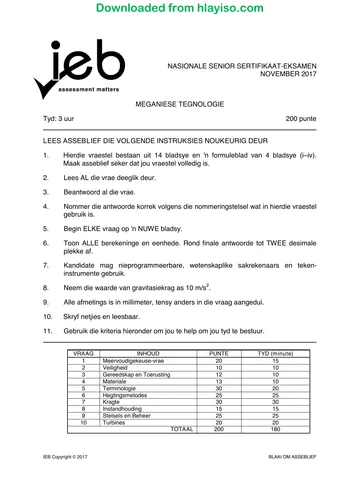
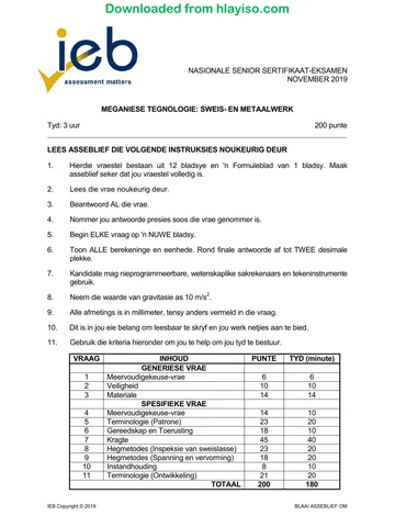
Mechanical Technology Grade 12 IEB 2017 Memo
IEB Grade 12 Mechanical Technology memorandum from the 2017, 16 pages. Read online or get the free PDF download, question paper linked when available.
Publisher: IEB
Mechanical Technology · Grade 12 · 2017. Memorandum, 16 pages. Read online or download the PDF.
- Subject
- Mechanical Technology
- Grade
- Grade 12
- Document type
- Memorandum
- Year
- 2017
- Publisher
- IEB
- Curriculum
- IEB
- Pages
- 16
- File size
- 401.1 KB
Loading document…
Loading document…
1 of 16
Document textSearch extracted text and jump to a page.
Downloaded from hlayiso.com
NATIONAL SENIOR CERTIFICATE: MECHANICAL TECHNOLOGY – MARKING GUIDELINES Page 2 of 16
QUESTION 1 MULTIPLE-CHOICE QUESTIONS
1.1 C
1.2 B
1.3 B
1.4 D
1.5 D
1.6 C
1.7 D
1.8 A
1.9 A
1.10 D
1.11 D
1.12 C
1.13 A
1.14 D
1.15 A
1.16 A
1.17 B
1.18 C
1.19 A
1.20 B
IEB Copyright © 2017 PLEASE TURN OVER
Downloaded from hlayiso.com
NATIONAL SENIOR CERTIFICATE: MECHANICAL TECHNOLOGY – MARKING GUIDELINES Page 3 of 16
QUESTION 2 SAFETY
2.1 Personal safety – Spot welder
• Wear protective clothes.
• Wear safety glasses.
• Wear gloves.
2.2 Safety – Tensile tester
• Area around tester must be fenced off.
• Only one person in fenced-off area during test.
• Dial indicator must be mounted properly.
• Front of the indicator must touch the bottom of the tester.
• Shield must be over sample that is tested.
• For steel and duralumin the hand wheel must be turned only half a turn
at a time.
• For plastic a one-fifth turn is sufficient for first three turns.
2.3 Safety – Valve spring compressor
• Nose of spring compressor must fit tightly over valve spring retainer.
• Specifications must be determined before spring compressor is used.
• Do not compress the spring more than what is prescribed in the
specifications.
2.4 Safety – Bearing and gear puller
• Make sure that the puller is the correct one for the task.
• Do not hit the puller with a hammer.
• Use the correct spanner to tighten the clamp and to pull off the object.
• Make sure that the puller is used at 90° to the work piece.
• Legs must not be worn out.
• Make sure that the clamps do not slip and cause injuries.
• Use a screen to prevent injuries.
• Do not stand directly behind the puller – this may cause injuries.
IEB Copyright © 2017 PLEASE TURN OVER
Downloaded from hlayiso.com
NATIONAL SENIOR CERTIFICATE: MECHANICAL TECHNOLOGY – MARKING GUIDELINES Page 4 of 16
QUESTION 3 TOOLS AND EQUIPMENT
3.1 Tests
3.1.1 The function of the oil pressure tester is to test the oil pressure in
an engine. Reason: To determine whether it is according to
specification.
3.1.2 The function of the hardness tester is to test hardness of metals.
Reason: It gives an indication of the metal's tensile strength.
3.1.3 The function of the torsion tester is to test the relationship
between momentum and torque applied to the material. Reason: To
examine the effect of material length and torsional deflection.
3.2 Screw thread micrometer reading
Reading = 2.00 mm
+ 0.12 mm
2.12 mm
3.3 Possible problems that may be diagnosed:
• Leaking piston rings
• Leaking valves
• Leaking cylinder head gasket
• Cracked engine block
• Cracked cylinder head
3.4 Multimeter tests
• Voltage
• Resistance
• Continuity
• Current
• Transistors
IEB Copyright © 2017 PLEASE TURN OVER
Downloaded from hlayiso.com
NATIONAL SENIOR CERTIFICATE: MECHANICAL TECHNOLOGY – MARKING GUIDELINES Page 5 of 16
QUESTION 4 MATERIALS
4.1 Iron-carbon equilibrium diagram
4.2 Advantage of nitration process on crankshaft surface:
• Very hard surface is obtained.
• It leaves some compression stress on the surface that counters metal
fatigue to some degree.
4.3 Machining of cams on camshaft:
Increases cams’ maximum resistance to wear.
IEB Copyright © 2017 PLEASE TURN OVER
Downloaded from hlayiso.com
NATIONAL SENIOR CERTIFICATE: MECHANICAL TECHNOLOGY – MARKING GUIDELINES Page 6 of 16
QUESTION 5 TERMINOLOGY
5.1 Calculation – Gib head key
van
Diameter of as
shaft
5.1.1 Width of
Wydte spy =
vankey
4
70
=
4
= 17,5 mm
Diameter
Diameter of
vanshaft
as
5.1.2 Thickness spy =
of key
Dikte van
6
70
=
6
= 11,67 mm
5.1.3 Length of key = 1,5 × diameter
= 1,5 × 70
= 105 mm
5.2 Milling cutter for spur gear:
• Involute cutter
5.3 Disadvantages of cutting screw thread – carriage method:
• The tip of the cutting tool, which is the weakest part of the cutting tool,
does most of the cutting.
• Because both sides of the cutting tool do the cutting, the chips curl into
each other. This may cause the screw thread to tear.
• A large load may damage the cutting tool/cutting edges.
• Slow method. (Any 2 × 1)
5.4 Indexing:
40
Indexing =
Indeksering
n
40
=
76
10 3
= ×
19 3
30
=
57
No full volle
Geen turns and 30 nie
draaie holes
enin30
a gate
57-hole plate
in 'n 57-gat-plaat
5.5 Advantages of up-cut milling
• A quick feed can be used.
• Vibration is less.
• Less stress on the cutter and arbor.
IEB Copyright © 2017 PLEASE TURN OVER
Downloaded from hlayiso.com
NATIONAL SENIOR CERTIFICATE: MECHANICAL TECHNOLOGY – MARKING GUIDELINES Page 7 of 16
• There is a positive pressure on the feed screw spindle and nuts
because the direction of the cutter is against the direction of the feed.
• Metals with hard shale start the cut below the shale where the metal is
softer. This extends the life of the cutter.
• More accurate during cutting.
• Better finish.
5.6 Purpose for using the straddle-milling method
• To mill the heads of square and hexagon bolts.
5.7 Milling machine set-up for keyway
• Fit a milling cutter with staggered teeth on the arbor.
• Fasten the workpiece in the chuck of the dividing head.
• If the workpiece is rectangular, move table to get workpiece in required
position.
• Hold the end of steel ruler against the side of the cutter.
• Move saddle to set up cutter at correct distance from the side of the
workpiece.
• Use a piece of tissue paper as an indicator between workpiece and
cutter to mark point of contact.
• Lift the knee of milling machine until cutter tears away the tissue paper.
• Set the index plate with scale divisions to zero in relation to index line.
• Move the workpiece back from the cutter.
Side and face cutter
Arbor
Workpiece
5.8 Function of screw thread micrometer
• To measure pitch diameter of a screw thread.
5.9 Lead of a screw thread is
• distance that a nut moves forwards on the screw thread.
• all along the screw thread.
• when it is turned through one full revolution.
IEB Copyright © 2017 PLEASE TURN OVER
Downloaded from hlayiso.com
NATIONAL SENIOR CERTIFICATE: MECHANICAL TECHNOLOGY – MARKING GUIDELINES Page 8 of 16
QUESTION 6 JOINING METHODS
6.1 Shielding gas
• It forms the arc plasma, stabilises the arc on the metal being welded
and protects the arc and molten pool.
• Prevents atmospheric contamination.
• Prevents excessive spatter.
6.2 Relationship between voltage and wire feed
Higher voltage causes a higher melting rate, therefore a higher feed rate is
needed.
6.3 Porosity in an MIG welding joint
• Atmospheric contamination
• Surface contamination
• Rusted MIG welding wire
• Strong wind (e.g. welding outside)
• Gas flow too high
• Incorrect welding technique
6.4 6.41 Porosity
• Use correct current setting.
• Maintain a longer arc.
• Use correct welding rods.
• Check for impurities – surface.
• Shield the welding process.
• Correct welding technique.
6.4.2 Lack of fusion
• Use the correct welding technique.
• Use the correct size welding rod.
• Use the correct current setting.
• Prepare the plate bevel (V-gap) correctly.
6.5 Destructive tests
6.5.1 Free-bend test
• Measures the ductility of the weld deposit or the heat-affected
area adjacent to the weld joint. OR
• Determines the percentage elongation of the weld metal.
6.5.2 Nick break test
• Determines the internal quality of the weld metal OR can indicate
internal defects.
IEB Copyright © 2017 PLEASE TURN OVER
Downloaded from hlayiso.com
NATIONAL SENIOR CERTIFICATE: MECHANICAL TECHNOLOGY – MARKING GUIDELINES Page 9 of 16
6.6 Advantage of ultrasonic testing versus similar tests
• System is fast.
• Results almost immediately available.
• No additional material needed.
• Test piece is not damaged.
6.7 Requirements for an acceptable welding joint
• Profile shape – profile must blend smoothly with adjacent surface.
• Surface uniformity – total length of the welding joint’s surface must be
uniform.
• Overlapping – there may be no overlapping at the toe of the welding
joint.
• Undercutting – no undercutting may occur in welding joints.
• Penetration bead – butt welding joints coming from one side only and
manufactured without a support beam may have a slight penetration
bead.
• Root gap – butt welding joints coming from one side only and without a
support beam may have a root opening.
• Free of cracks – the weld metal, heated area and surrounding base
metal must display no cracks.
• Surface defects – no surface defects must be visible.
6.8 Transmitter-receiver unit
• A unit that is used to transmit a sound wave and then listen as a
receiver to the ultrasonic wave as the metal reflects it back. OR
• To show defects.
IEB Copyright © 2017 PLEASE TURN OVER
Downloaded from hlayiso.com
NATIONAL SENIOR CERTIFICATE: MECHANICAL TECHNOLOGY – MARKING GUIDELINES Page 10 of 16
QUESTION 7 FORCES
7.1 7.1.1 Sum of vertical and horizontal components
Force Horizontal components Vertical components
160 N X = 160 cos 0° = 160 N Y = 160 sin 0° = 0 N
75 N X = 75 cos 150° = –64,951 N Y = 75 sin 150° = 37,5 N
200 N X = 200 cos 225° = –141,421 N Y = 200 sin 225° = –141,421 N
90 N X = 90 cos 240° = –45 N Y = 90 sin 240° = –77,942 N
–91,372 N –181,863 N
7.1.2 Resultant force
R² = X² + Y²
R² = 91,372² + 181,863²
R² = 41 422,99315
R = √41 422,99315
R = 203,53 N
7.1.3 Direction of resultant force
Sum Y
tan Ø =
Sum X
181,863
tan Ø =
91,372
tan Ø = 1,99
Angle = 63,32°
7.2 Magnitude of force
Stress = Pa
Diameter = m
Force = N
krag
force
Spanning =
Stress
area
=Krag = Stress
Force Spanning×× Area
Area
π × 0,0352
=
krag 5200 000 ×
4
krag = 5,2 ×10 × 9,621127502 x10 −4
6
= 5002,99 N
krag = 5 kN
IEB Copyright © 2017 PLEASE TURN OVER
Downloaded from hlayiso.com
NATIONAL SENIOR CERTIFICATE: MECHANICAL TECHNOLOGY – MARKING GUIDELINES Page 11 of 16
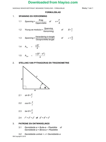
7.3 Stress and strain
E = Break stress / Break point
7.4 Reactions
Taking moments around A
A × 7,5 = (600 × 4) + (225 × 6,25) + (400 × 8,5)
7206,25
A=
7,5
A = 960,833 N
Taking moments around B
(225 × 1,25) + (600 × 3,5) = (B × 7,5) + (400 × 1)
281,25 + 2 100 = 7,5B + 400
1981,25
B=
7,5
B = 264,166 N
IEB Copyright © 2017 PLEASE TURN OVER
Downloaded from hlayiso.com
NATIONAL SENIOR CERTIFICATE: MECHANICAL TECHNOLOGY – MARKING GUIDELINES Page 12 of 16
QUESTION 8 MAINTENANCE
8.1 Preventative maintenance
Preventative maintenance is the systematic inspection, detection and
correction of systems before they break down.
8.2 Authoritative body in oil classification
American Petroleum Institute (API)
8.3 Pour point
Pour point is the lowest temperature at which a liquid remains a fluid.
8.4 Cutting fluid mixture
• Cutting fluid consists of soluble oil and water.
8.5 Maintenance of belt drive systems
• Belts tend to stretch after a period of use, therefore they must be
tightened from time to time and checked for correct alignment.
or
• To transmit maximum power/torque without any slippage.
8.6 Reason for machining flywheel
• The clutch plate presses against the flywheel. As a result of friction
between the clutch and the flywheel grooves are formed in the flywheel.
The grooves/cracks will then have to be removed through a precision
machining process before the new clutch plate is fitted.
or
• To ensure maximum coefficient of friction on area between clutch plate
and flywheel.
or
• To reduce wear on a new clutch plate.
8.7 Lubrication of hypoid gears
• It is difficult to lubricate hypoid gears because they shift over each other
rather than roll, this action therefore rubs off the lubrication.
IEB Copyright © 2017 PLEASE TURN OVER
Downloaded from hlayiso.com
NATIONAL SENIOR CERTIFICATE: MECHANICAL TECHNOLOGY – MARKING GUIDELINES Page 13 of 16
QUESTION 9 SYSTEMS AND CONTROL
9.1 Gear drives
9.1.1 Number of teeth of idler gear
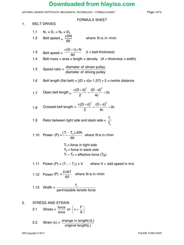
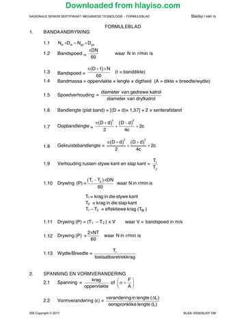
NA ×TA =NB ×TB
NA ×TA
TB =
NB
600× 40
=
800
teeth
= 30 tande
9.1.2 Rotation frequency of the driven gear
NB ×TB =NC ×TC NA ×TA =NC ×TC
NB ×TB NA ×TA
NC = NC =
TC TC
OR
800× 30 600× 40
= =
60 60
= 400r/min = 400r/min
9.2 Pulley drives
9.2.1 Diameter of the driven pulley
N1×D1 =N2 ×D2
N1×D1
D2 =
N2
8,2×700
=
14
= 410 mm
9.2.2 Power transmitted:
T1
=2,5
P= ( T1 − T2 ) πDn T2
P=(400 − 160) π × 0,7 × 8,2 400
T2 =
= 4327,86 Watts 2,5
= 4,32 kW = 160 N
OR
IEB Copyright © 2017 PLEASE TURN OVER
Downloaded from hlayiso.com
NATIONAL SENIOR CERTIFICATE: MECHANICAL TECHNOLOGY – MARKING GUIDELINES Page 14 of 16
P = ( T1 − T2 ) πdn
T1
P =(400 − 160) π × 0,41×14 =2,5
T2
= 4327,82 Watts
= 4,32 kW 400
T2 =
2,5
= 160 N
9.3 Hydraulics
9.3.1 Pressure in the system
Area A
ΠD²
A=
4
A = 0,7853981 × (0,06²)
A = 2,8274 × 10⁻³ m²
F
P=
A
600
P=
2,8274 × 10 −3
P = 212 206,5908 Pa
9.3.2 Distance X that moves piston B
Area B
ΠD²
A=
4
A = 0,7853981 × (0,2²)
A = 0,031415926 m²
Distance of A × Area of A = Distance × X × Area of B
0,065 × 0,0028274
X=
0,031415926
X = 5,84999 × 10⁻³
X = 5,84 mm
Distance X = 5,84 mm
IEB Copyright © 2017 PLEASE TURN OVER
Downloaded from hlayiso.com
NATIONAL SENIOR CERTIFICATE: MECHANICAL TECHNOLOGY – MARKING GUIDELINES Page 15 of 16
9.4 Airbags
These may be seen as a passive safety device because the driver and
passengers do not have to activate the airbags or do anything to be
protected by the airbags.
QUESTION 10 TURBINES
10.1 Reaction turbine
• Francis
• Kaplan
• Tyson
• Gorlov
10.2 Runaway speed
Runaway speed refers to a turbine’s rotational speed at full flow without
any load.
10.3 Controlling speed of steam turbine
To prevent the turbine rotor from resulting in an overspeed trip, and
continuing to accelerate and breaking apart.
10.4 Advantages of gas turbine
• Smooth operation owing to fewer moving parts.
• No moving parts such as a piston that causes internal friction and wear.
• Easy starting.
• Uses a wide range of fuels.
• No water cooling system is required.
• Non-toxic exhaust gasses do not cause pollution problems.
• Requires little routine maintenance.
• Very high power-to-weight ratio compared to piston engine.
• Moves only in one direction with much less vibration than a piston
engine.
• Low operating pressure.
• High operating speed.
• Low lubrication cost and consumption.
IEB Copyright © 2017 PLEASE TURN OVER
Downloaded from hlayiso.com
NATIONAL SENIOR CERTIFICATE: MECHANICAL TECHNOLOGY – MARKING GUIDELINES Page 16 of 16
10.5 Sections of turbocharger
• Turbine section
• Compressor section
10.6 Volumetric efficiency
The ability to fill the cylinder with air.
10.7 Altitude above sea level
• At high altitude less oxygen is available for combustion.
• Power losses occur.
10.8 Advantages of centrifugal charger over the twin-screw supercharger
• Centrifugal chargers are small/compact.
• Centrifugal chargers are lightweight.
• They are mounted on the front of the engine instead of on top.
• Twin-screw superchargers are mounted on top of the engine, which
requires space.
• Rotors of a twin-screw supercharger require very accurate and precision
manufacturing.
10.9 Purpose of the recuperator
A recuperator is a heat exchanger that transfers exhaust heat before
combustion to the compressed air.
Total: 200 marks
IEB Copyright © 2017
Study this subject
Revise the topics in this paper, then practise them question by question.
Recommended for this subject
More papers and memos for this grade and subject.
MemorandumIEB
Mechanical Technology Grade 12 IEB 2019 Memo (Afrikaans)
MemorandumIEB
Mechanical Technology Grade 12 IEB 2019 Memo
MemorandumIEB
Mechanical Technology Grade 12 IEB 2017 Memo (Afrikaans)
Information sheetIEB
Mechanical Technology Grade 12 IEB 2019 Information Sheet
Information sheetIEB
Mechanical Technology Grade 12 IEB 2019 Information Sheet (Afr)
Question paperIEB
Mechanical Technology Grade 12 IEB 2019 Question Paper
Related documents
Information sheetIEB
Mechanical Technology Grade 12 IEB 2017 Information Sheet
Information sheetIEB
Mechanical Technology Grade 12 IEB 2017 Information Sheet (Afr)
Question paperIEB
Mechanical Technology Grade 12 IEB 2017 Question Paper
Question paperIEB
Mechanical Technology Grade 12 IEB 2017 Question Paper (Afr)
Question paperIEB