
Downloaded from hlayiso.com
INSTRUCTIONS AND INFORMATION
1. The question paper consists of FOUR questions.
2. Answer ALL the questions.
3. All drawings must be drawn to scale 1 : 1, unless stated otherwise.
4. The questions must be answered on the answer sheets provided.
5. All the answer sheets must be re-stapled in numerical sequence and handed in
irrespective of whether the question was answered or not.
6. Careful time management is essential in order to complete all the questions.
ISEBE LEMFUNDO LEMPUMA KOLONI 7. Print your name in the block provided on every answer sheet.
EASTERN CAPE EDUCATION DEPARTMENT 8. All answers must be drawn accurately and neatly.
OOS-KAAP ONDERWYSDEPARTEMENT 9. Any details or dimensions not given must be assumed in good proportion.
FOR OFFICIAL USE ONLY
NATIONAL MODERATED
MARK
SENIOR CERTIFICATE
1
2
3
4
TOTAL
GRADE 11
2 0 0
ENGINEERING GRAPHICS AND DESIGN P1
NOVEMBER 2015
COMPLETE THE FOLLOWING:
NAME
NAME
MARKS: 200
EXAMINATION CENTRE
TIME: 3 hours
*IGRDSE* EXAMINATION CENTRE
This question paper consists of 6 pages.
Copyright reserved
Please turn over 1
Skip to contentAll 2015 papers 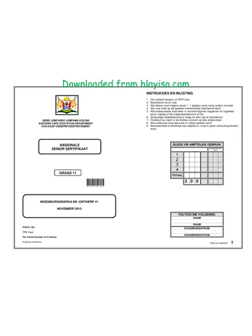
View all
Engineering Graphics and Design Grade 11 P1 2015 QP (Eng)
Grade 11 Engineering Graphics and Design Paper 1 question paper from the Eastern Cape November 2015 (English), 6 pages. Read online or download the free PDF.
Engineering Graphic And Design · Grade 11 · Eastern Cape November · 2015. Question paper, 6 pages. Read online or download the PDF.
- Subject
- Engineering Graphics and Design
- Grade
- Grade 11
- Document type
- Question paper
- Year
- 2015
- Exam period
- Eastern Cape November
- Paper
- 1
- Curriculum
- CAPS
- Pages
- 6
- File size
- 1.5 MB
Free to read online, no sign-up needed
Loading document…
Loading document…
1 of 6
This exam
Eastern Cape November 2015
- Paper 1Question paper · EngQuestion paper · AfrMemo
- Paper 2Question paper · EngQuestion paper · AfrQuestion paperQuestion paper (2)Question paper (3)Question paper (4)Question paper (5)Question paper (6)Question paper (7)Question paper (8)Question paper (9)Question paper (10)Question paper (11)Question paper (12)
- Other filesQuestion paper · EngQuestion paper · AfrQuestion paperQuestion paper (2)Question paper (3)Question paper (4)Question paper (5)Question paper (6)Question paper (7)Question paper (8)Question paper (9)Question paper (10)Question paper (11)Question paper (12)Question paper (13)Question paper (14)
Document textSearch extracted text and jump to a page.
Engineering Graphics and Design/P1
EC DoE/NOVEMBER 2015
> e
ie & QUESTION 1: CIVIL ANALYTICAL
Given:
L © A floor plan of a house
1) A table with questions referring to the drawing.
Instructions:
Answer the questions by neatly printing the answers
in the space provided on the table. [30]
f f 1
i E 1 C
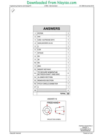
AIA QUESTIONS ANSWERS
els
| DINING ROOM | 4, | Identify TWO deliberate design errors in 2
the bathroom.
2 | Identify ONE deliberate drawing error in 1
LOUNGE 4 bedroom 2.
> ‘ Identify ONE deliberate drawing error in
iz KITCHEN 3 | the Ktehen ° 1
| What drawing feature has been omitted 4
from all the walls on the floorplan?
7] r] r 5. | What does BIC stand for? 1
6 |Name the drawing feature at 1 1
! 7. | What do the lines at 2 indicate? 1
3 BIC
8 bA 8 | Identify the drawing error at 3. 1
fe In the space provided at 4, on the plan,
BIC 9 | draw neatly in freehand, the graphical 4
symbol for a double kitchen sink.
0 In the space provided at 5, on the plan,
cg) BEDROOM 2 10 | draw neatly in freehand, the graphical 3
c BEDROOM 1 symbol for a shower.
f=} "1 What view of the house will be seen in 4
g the direction of the arrow at 6?
12 | What is the scale of the drawing? 1
(| BATHROOM 4g | Whats the thickness of the load 1
L bearing walls in mm?
. oo 44 | Determine the floor area of bedroom 2 3
in m?
: 1
—__—_—__t 45 | Determine the perimeter of the house in 3
meters.
220 110 3 Measure the length of a bedroom
4g | Window on the drawing and detemine 3
4200 2904 its length in meters according to a scale
12000 of 1: 50.
17 | What does the symbol at 7 indicate? 1
49 | Neatly print the name of the view in the 1
a space provided above the scale.
SCALE 1: 50 30
NAME
NAME =)
Copyright reserved
Please tum over
Engineering Graphics and Design/P1
Loe
“e
SL-
aK
EC DoE/NOVEMBER 2 015
QUESTION 2: SECTIONING OF SOLIDS.
Given:
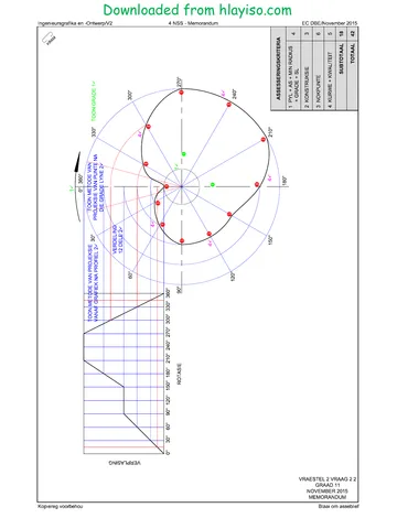
© The front view and top view of a right regular hexagonal
pyramid cut by an inclined plane VT.
* A starting point A, for drawing the top view.
Instructions:
* Draw the given front view.
* Draw the sectional top view without hidden detail.
* Draw the sectional right view without hidden detail.
* Project the true shape of the cut surface.
Show all constructions [34]
ASSESSMENT CRITERIA
1 Front view 7
2 Sectional top view 7
3 Sectional right view | 10
4 True shape 6
5 Constructions 4
TOTAL 34
NAME
NAME wy
Copyright reserved
Please tum over
Engineering Graphics and Design/P1 N
oy .
©
EC DoE/NOVEMBER 2015
QUESTION 3: PERSPECTIVE
Given:
A plan and elevations of a braai area, as well as the Picture Plane
(PP), Horizon Line (HL), Ground Line (GL) and Station Point (SP)
Instructions:
* Determine the vanishing points and label them.
* Draw the two point perspective view of the braai area.
Note:
No hidden detail must be shown.
Show all construction lines. [38]
PP
HL
T T
| |
/ \
GL
NAME
ASSESSMENT CRITERIA
1 Vanishing points 4
2 Constructions 4
3 Floor and seat 16 x > 8
4 Braai and chimney 14 x} 7
5 Sides 30 x4 15
TOTAL 38
NAME T/
Copyright reserved
Please tum over
Engineering Graphics and Design/P1
“ e
DOOR AND WINDOW SCHEDULE
WINDOWS
2400 1200
al \. Ya wl TN /
5 L \ = / \,
wi w2
NOTE
220 X 110 BRICKS ON EDGE SILL BELOW
WINDOWS
LINTEL
PRECAST CONCRETE LINTEL: 110 x 75 mm
DOORS
L TOFIT L TOFIT
GARAGE DOOR (D2)
HOLLOW CORE DOOR (D1)
DIMENSIONS OF SANITARY FIXTURES.
310
ITs
crit
700
700
{300
wi
N
__ CEILING HEIGHT _ _ _ _ _ _ _ _ _
Tt [~ WINDOW HEIGHT
WINDOW WINDOW
2 ra
| b, WINDOW SILL u
220 0 2
. tt oe
wi
tu L] :
A\ w2 we: B
A — BATHROOM KITCHEN
TILES TILES
1 D1 7 Dt
GARAGE
D1
LIVING ROOM BEDROOM
[rassace See ore
D1
D1
a
CL _____| wW1
EC DoE/NOVEMBER 2015
QUESTION 4: CIVIL DRAWING
Given:
* A schematic floor plan and a schematic sectional
elevation of the outline of the primeter of a house, and
the grahical symbols of all the fixtures in the bathroom.
* A door and window schedule
* An answer sheet on page 6 showing an incomplete floor
plan.
Instructions:
Use answer sheet 4 and the information on page 5 to
draw to a scale of 1: 50, the following views:
¢ The completed floor plan
* The sectional elevation on cutting plane A-A, to the
given specifications below:
SPECIFICATIONS:
THE FLOOR PLAN
Add the following features to the floor plan:
©The missing walls and hatching detail
*The missing doors and windows with detail
©The cutting plane. Label the cutting plane A-A.
* Label all the rooms and its floor finishes.
THE SECTIONAL ELEVATION
Add the following features to the sectional elevation:
* The complete foundation, walls, screed and floor slab
detail
* The lintels above the window
* The complete window detail
* ALL necessary hatching
*All sanitary fixtures as graphical symbols
*Label the DPC
* Label the NGL
* Label the sectional elevation:
SECTIONAL ELEVATION A-A
NOTE:
* ALL substructure hatching may be done in freehand.
* ALL drawing must comply with the guidelines contained
in the SABS 0143. [98]
TERMINOLOGY
Schematic diagram: A diagram that shows the main
features or relationships but not the details.
NAME.
NAME,
Engineering Graphics and Design/P1
EC DoE/NOVEMBER 2015
FLOOR PLAN
1. HATCHING 13
2 DOORS AND WINDOWS 24
3 ROOMS AND FLOOR FINISH] 6
4 CUTTING PLANE 2
SUBTOTAL 45
SECTIONAL ELEVATION
‘1 FOUNDATION AND WALLS | 24
2 WINDOWS AND LINTELS 12
3 HATCHING 12x } 6
4 SANITARY FIXTURES. 6
5 LABELS 5
SUBTOTAL 53
TOTAL 98
NAME,
NAME, 6 )
Copyright reserved
Please tum over
Study this subject
Recommended for this subject
Question paper
Engineering Graphics and Design Grade 11 P1 2015 QP (Afr)
Memorandum
Engineering Graphics and Design Grade 11 P1 2015 Memo
Question paper
Engineering Graphics and Design Grade 11 2015 QP (Eng)
Question paper
Engineering Graphics and Design Grade 11 2015 QP (Afr)
Question paper
Engineering Graphics and Design Grade 11 2015 QP (Afr)
Question paper
Engineering Graphics and Design Grade 11 2015 QP (Eng)
More from Grade 11 Engineering Graphics and Design
Annual teaching plan
Gr 11 EngGraph Des ATP 2023 24
Memorandum
Engineering Graphics and Design Grade 11 P1 2022 Memo (Afr)
Memorandum
Engineering Graphics and Design Grade 11 P2 2022 Memo (Afr)
Memorandum
Engineering Graphics and Design Grade 11 P2 2022 Memo (Eng)
Memorandum
Engineering Graphics and Design Grade 11 P1 2022 Memo (Eng)
Memorandum