
Downloaded from hlayiso.com
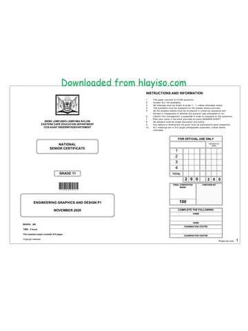
INSTRUCTIONS AND INFORMATION
ISEBE LEMFUNDO LEMPUMA KOLONI
EASTERN CAPE EDUCATION DEPARTMENT
OOS-KAAP ONDERWYSDEPARTEMENT
FOR OFFICIAL USE ONLY
NATIONAL MODERATED
MARK
SENIOR CERTIFICATE
1
2
3
4
GRADE 11 TOTAL
2 0 0 2 0 0
FINAL CONVERTED CHECKED BY
*IGRDSE1* MARK
ENGINEERING GRAPHICS AND DESIGN 100
PAPER 1
COMPLETE THE FOLLOWING:
NOVEMBER 2019 NAME
NAME
MARKS: 200
EXAMINATION CENTRE
TIME: 3 hours
This question paper consists of 6 pages.
EXAMINATION CENTRE
Copyright reserved
Please turn over 1
Skip to contentAll 2019 papers 
View all
Engineering Graphics and Design Grade 11 P1 2019 QP (Eng)
Grade 11 Engineering Graphics and Design Paper 1 question paper from the Eastern Cape November 2019 (English), 6 pages. Read online or download the free PDF.
Engineering Graphic And Design · Grade 11 · Eastern Cape November · 2019. Question paper, 6 pages. Read online or download the PDF.
- Subject
- Engineering Graphics and Design
- Grade
- Grade 11
- Document type
- Question paper
- Year
- 2019
- Exam period
- Eastern Cape November
- Paper
- 1
- Curriculum
- CAPS
- Pages
- 6
- File size
- 863.9 KB
Free to read online, no sign-up needed
Loading document…
Loading document…
1 of 6
This exam
Eastern Cape November 2019
Document textSearch extracted text and jump to a page.
Engineering graphics and design / P1
Downloaded from hlayiso.com NSC EC / November 2019
AP
LE
FIGURE 1: FIGURE 3: QUESTION 1A: ANALYTICAL (CIVIL)
ST
Given:
1 Figure 1: Incomplete wall and foundation detail.
Figure 2: A view of a floorplan with measurements (not to scale).
2 Figure 3: The plan view of the SANS 10143 symbol for steps.
3 Figure 4: A symbol with a specific meaning.
4 Instructions:
FIGURE 4: Complete the table below by neatly answering the questions, which refer to the accompanying figures (1 to 4) and
5 civil content. [35]
6 1 What SI-unit was used for the dimensions in figure 2? 1
ALL EXISTING MATERIALS 1
FIGURE 2: ANSWER 5: ANSWER 6: NEW WOOD 1
14500 In which colours must the following features be shown NEW DRAINAGE / SEWERAGE 1
2 on a civil drawing according to the SANS 10143? NEW MASONRY 1
NEW GLASS 1
FLOOR PLAN NEW CONCRETE 1
NTS
1
10000
1
2 1
2500
Name the parts from 1 to 6 of the incomplete wall and 3 1
3
2500
foundation detail shown in figure 1. 1
4
5 1
5000
6 1
ANSWER 9.1 ANSWER 9.2 ANSWER 9.3 4 What does the abbreviation NTS, in figure 2, stand for? 1
In the space provided (ANSWER 5) determine the total perimeter of the house, in figure 2, in meters.
5 3
Show all calculations.
In the space provided (ANSWER 6) determine the total area of the house, in figure 2, in square meters.
6 4
Show all calculations.
7 What does the arrow in figure 3 mean? 1
8 Name the symbol in figure 4. 1
In the space provided (ANSWER 9.1 - 9.3), draw, in neat freehand, the front view and top view of the SANS 10143
9 graphical symbol for the following: 12
9.1 BATH; 9.2. SINGLE SINK; 9.3 TOILET
TOTAL: 35
BATH SINGLE SINK TOILET
FIGURE 6: ANSWER 1B:
FIGURE 5:
PUSH
M QUESTION 1B: ELECTRONICS SWITCH
"PTM"
Given: MARKS
Figure 5: A table with symbols of electronic components. LED
Figure 6: A diagram with labels of a touch sensor. Q 1A 35
9V
BATTERY
Q 1B 6
Instructions: RESISTOR
Draw the electronic diagram with the correct electronic TOT 41
symbols, in free hand, in the space provided
NPN
+ under ANSWER 1B.
[6]
TRANSISTOR
NAME
ELECTRONIC COMPONENTS: SYMBOLS NAME 2
Copyright reserved Please turn over
Engineering graphics and design / P1
Downloaded from hlayiso.com
NSC EC / November 2019
AP
LE
QUESTION 2: TRANSITION PIECE
ST
Given:
x The top view and front view of a square to triangle transition
piece, drawn in first-angle orthographic projection.
x An isometric help view of the transition piece.
x Axis XY and -X1Y1.and a starting point c and c1.
x Starting point ABC and the direction of development.
Instructions:
X
1
Draw, to scale 1 : 1, the following views of the transition piece.
Start at C, C1.
2.1 The given top view.
2.2 The given front view.
2.3 The left view.
2.4 The development of the transition piece, starting and
ending with seam AB. The direction of the arrow P indicates
the direction of the development.
Show ALL constructions.
[36]
30
a d
80
c
b c
X Y X Y
p c1d1
c1 a1b1
60°
60
60
C A
ASSESSMENT CRITERIA
CONSTRUCTIONS +
D 1 PLACING
4
2 TOP VIEW 6
Y
1 3 FRONT VIEW 5
P
4 LEFT VIEW 4
A
B
P 5 DEVELOPMENT 17
TOTAL 36
C
B
NAME
ISOMETRIC VIEW:
NAME 3
Copyright reserved Please turn over
Engineering graphics and design / P1
Downloaded from hlayiso.com
NSC EC / November 2019
LE
AP
ST
QUESTION 3: PERSPECTIVE
Given:
Three views of a HOUSE WITH A PORCH and the
information needed to draw a two-point perspective
drawing. ASSESSMENT CRITERIA
PP − Picture plane
HL − Horizon line 1 CONSTRUCTION + VPs 6
GL − Ground line
SP − Station point 2 ROOFS 7
Instructions: 3 WALLS + BRAAI + 15
CHIMNEY
Complete the perspective drawing.
4 WINDOW + DOOR 8½
x Align the drawing sheet with the ground line (GL).
x Determine and label the vanishing points. 5 PORCH 4½
x Show ALL necessary construction.
x NO hidden detail is required.
[41]
TOTAL 41
PORCH
PORCH
PP PP
HL HL
PORCH PORCH GL
GL
NAME
SP
NAME 4
Copyright reserved Please turn over
Engineering graphics and design / P1
Downloaded from hlayiso.com NSC EC / November 2019
LE
AP
ST QUESTION 4: CIVIL DRAWING
SLIDING DOOR OPENING
DOOR AND WINDOW SCHEDULE Given:
WINDOW OPENING
SLIDINGDOOR AND -FRAME (SD)
x The incomplete SOUTH ELEVATION of a proposed new
GARAGE DOOR OPENING
dwelling, showing the walls, step as well as window-,
1500 TO FIT
2050 2150
GARAGE FINISHED FLOOR door- and roll up garage door openings.
LEVEL
400 x The incomplete floor plan showing the walls, position of
GROUND LINE the doors, windows and sanitary fixtures.
x The incomplete foundation and wall detail.
STEP RAMP 200 x Room designations and floor finishes.
FINISHED FLOOR LEVEL x A door, window and garage door schedule.
2050
INCOMPLETE SOUTH ELEVATION
x A table of sanitary fixtures.
x The floor plan of the new dwelling as well as a breakline
and the natural ground level in the south elevation, drawn
KITCHEN CABINET to scale 1:50 and the starting point and breakline for the
HEIGHT: 800MM
FEATURES sectional view to scale 1:20 (on page 6).
SLIDINGDOOR NOTES
W2 W2 W1 FRAMES 50 mm
D1 DOOR
WC S TO FIT 1000 Instructions:
B SD SLIDING DOOR
W1 WINDOW Answer this question on page 6.
A D1 A W2 WINDOW
WB 3 GD ROLL UP GARAGE DOOR 4.1 Using the given incomplete floor plan, draw in first-angle
4 A 800
2 orthographic projection and to scale 1 : 50, the following
SH FIXTURES 350 B
views of the new dwelling:
2050
BIC D1
WC TOILET WINDOW (W1)
D1 D1 W1
B BATH 4.1.1 THE COMPLETE FLOOR PLAN
D1 WB WASH BASIN 1500 Add the following features to the drawing:
BIC SH SHOWER 650 x ALL doors and windows.
S SINK
6 BIC BUILT IN CUPBOARD
x ALL fixtures as indicated by the abbreviations.
450 x ALL hatching detail.
ROOM DESIGNATIONS DOOR AND -FRAME (D1) A
1 5 100
1500
FLOOR FINISHES DOOR FRAME PROFILE B 4.1.2 THE SOUTH ELEVATION
1. BEDROOM CARPET
WINDOW NOTES
A Show the following features on the drawing:
2. BEDROOM CARPET 50 A = OPENING SIDE x The outside walls, step, window-, door- and roll up garage
W2 GD
3. BATHROOM TILE 400 B
door detail below the given breakline.
B = FIXED PANEL
4. KITCHEN TILE
5. LIVING ROOM TILE
FRAMES 50 mm x The finished floor level.
SD WINDOW (W2)
6. GARAGE GRANO WINDOW SILL: 220 x 110 mm
STEP
WINDOW SILL: BRICK ON EDGE UNDER ALL 4.2 Draw in the space provided on page 6 to scale 1 : 20, a
RAMP
INCOMPLETE FLOORPLAN WINDOWS DETAILED SECTION according to cutting plane A-A of the
240 2550 area in the ellipse shown on the floor plan.
Show the following features:
110 x The complete foundation, external wall and door detail.
2 X 120 x 100 mm LINTEL x The lintels above the door.
ABOVE DOOR- AND
WINDOW OPENINGS R200 ROLL UP GARAGE DOOR (GD) x The partial window in the kitchen.
x A partial kitchen cabinet.
x ALL hatching detail. ALL substructure hatching may be
SANITARY FIXTURES drawn neat in freehand.
500
2400 400 Label the following:
400
x The south elevation and scale.
2050
200
850 850 x The room designations and floor finishes.
750
25 mm 100 x Using the correct abbreviations, label the following
25 mm 400 390
SCREED FLOOR LEVEL features in the correct view: natural ground level, finished
100 SCREED
floor level and damp proof course.
100
300 400 600
200
1100 500 350
550 GROUND LEVEL 800 NOTE:
250 ALL drawings must comply with the guidelines and graphical
550 1200
200 800 1400 symbols contained in the SANS 10143. [82]
600 WASH BASIN TOILET SINK
400 SHOWER
(WB) (WC) (S) BATH (B)
(SH)
INCOMPLETE NON LOAD NAME
BEARING WALL AND INCOMPLETE LOAD BEARING
STARTING POINT FOR DETAILED SECTION
FOUNDATION DETAILS WALL AND FOUNDATION DETAILS
NAME 5
Copyright reserved Please turn over
Engineering graphics and design / P1
Downloaded from hlayiso.com
NSC EC / November 2019
PENALTIES
LE
AP
ST
1 INCORRECT OVERALL SCALE
2 INCORRECT POSITIONING OF VIEWS
3 NON-ALIGNMENT OF VIEWS
TOTAL PENALTIES (-)
ASSESSMENT CRITERIA
FLOOR PLAN
NGL NGL
1 DOORS +
WINDOWS 20
2 FIXTURES 9
3 HATCHING 3
4 LABELS 6
SUB TOTAL 38
SOUTH ELEVATION
1 WALLS + STEP +
FFL 5
2 WINDOW + DOOR +
GARAGE DOOR 10
3 LABELS 4
SUB TOTAL 19
DETAILED SECTION
1 FOUNDATION +
WALL + FLOOR 9
2 DOOR + LINTEL +
WINDOW +
KITCHEN CABINET
8
3 HATCHING 5
4 LABELS 3
SUB TOTAL 25
TOTAL 82
PENALTIES (-)
FINAL TOTAL
STARTING POINT FOR
DETAILED SECTION
DETAILED SECTION ON A-A
FLOORPLAN SCALE 1 : 20
SCALE 1 : 50
NAME
NAME 6
Copyright reserved
Study this subject
Recommended for this subject
Question paper
Engineering Graphics and Design Grade 11 P1 2019 QP (Afr)
Memorandum
Engineering Graphics and Design Grade 11 P1 2019 Memo
Question paper
Engineering Graphics and Design Grade 11 P2 2019 QP (Afr)
Question paper
Engineering Graphics and Design Grade 11 P2 2019 QP (Eng)
Question paper
Engineering Graphics and Design Grade 11 P1 2020 QP (Eng)
Question paper
Engineering Graphics and Design Grade 11 P1 2020 QP (Afr)
More from Grade 11 Engineering Graphics and Design
Annual teaching plan
Gr 11 EngGraph Des ATP 2023 24
Memorandum
Engineering Graphics and Design Grade 11 P1 2022 Memo (Afr)
Memorandum
Engineering Graphics and Design Grade 11 P2 2022 Memo (Afr)
Memorandum
Engineering Graphics and Design Grade 11 P2 2022 Memo (Eng)
Memorandum
Engineering Graphics and Design Grade 11 P1 2022 Memo (Eng)
Memorandum