
Downloaded from hlayiso.com
GRAAD 12
NATIONAL
SENIOR CERTIFICATE
GRADE 12
ELECTRICAL TECHNOLOGY: DIGITAL
NOVEMBER 2018
MARKS: 200
TIME: 3 hours
This question paper consists of 15 pages, a 1-page formula sheet and
10 answer sheets.
Copyright reserved Please turn over
You're offline
Skip to contentQuestion paper %20(English)%20June%202025%20Question%20Paper--5422e67a-03a4-4202-ba9b-1b9ec9872537/v1-bc4ab06b657031de8079/card.webp)
%20Eng--870e3d22-85e9-42bd-890f-3ef1fd3333cf/v1-34f597b30020a0074782/card.webp)
%20Afr--98972424-ba56-4bbc-a319-fdfc1fec40f8/v1-90de7f1850adc8e5ce8c/card.webp)
%20Eng_hlayiso.com_--a68e616b-2683-467b-a87c-cbea669d5fc9/v1-29837375d7d876d15ee3/card.webp)
%20Eng_hlayiso.com_--f51bbc58-dd6c-4602-a333-adace247b202/v1-9f402b12ec5671c7e840/card.webp)
%20Afr_hlayiso.com_--53683d88-b757-4081-8090-9168158594ae/v1-9fcbaccf3fd4b1c0221f/card.webp)
%20Afr_hlayiso.com_--fb20ccd8-a161-46cc-8f82-61cf2d788665/v1-92e7c857a6ea8aa54ec7/card.webp)
%20Afr_hlayiso.com_--11dc7c93-2234-4876-9ed6-efcc8515dc4e/v1-0fac8e8bc375fd412ee2/card.webp)
%20FINAL%20Memo%20Afr_hlayiso.com_._hlayiso.com_--7f7082ac-82f3-4ba2-903c-f36daf9d4ddf/v1-f5c4a74754c6d3675d59/card.webp)
View all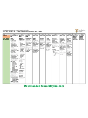
%20(English)%20June%202025%20Possible%20Answers--4302563e-89b7-4f54-8a21-63b2020e985f/v1-3e4c5b36e08cde219ac2/card.webp)
%20Afr--5f2b4850-fffb-4024-8f24-d74bd8677a25/v1-8feb81a6973919da05bd/card.webp)
%20MG%20Eng--200c3b27-716d-47b4-a29d-81caca0c5203/v1-d39bb264870ee531f16c/card.webp)
Electrical Technology Nov 2018 (Digitals) Eng hlayiso.com
Electrical Technology · Grade 12 · NSC November Exam · 2018. Question paper, 26 pages. Read online or download the PDF.
- Subject
- Electrical Technology
- Grade
- Grade 12
- Document type
- Question paper
- Year
- 2018
- Exam period
- NSC November Exam
- Pages
- 26
- File size
- 603.4 KB
Loading document…
Loading document…
1 of 26
Document textSearch extracted text and jump to a page.
Downloaded from hlayiso.com
Electrical Technology: Digital 2 DBE/November 2018
NSC
INSTRUCTIONS AND INFORMATION
1. This question paper consists of FIVE questions.
2. Answer ALL the questions.
3. Answer the following questions on the attached ANSWER SHEETS:
QUESTION 2.3.2
QUESTIONS 2.4.1, 2.5.2, 2.6.3, 2.7.4, 2.8.1, 2.8.2 and 2.9.1
QUESTION 3.1.3
QUESTIONS 4.3 and 4.5.2
4. Write your CENTRE NUMBER and EXAMINATION NUMBER on every
ANSWER SHEET and hand them in with your ANSWER BOOK, whether you
have used them or not.
5. Sketches and diagrams must be large, neat and fully labelled.
6. Show ALL calculations and round off answers correctly to TWO decimal
places.
7. Number the answers correctly according to the numbering system used in this
question paper.
8. You may use a non-programmable calculator.
9. Show the units for ALL answers of calculations.
10. A formula sheet is attached at the end of this question paper.
11. Write neatly and legibly.
Copyright reserved Please turn over
Downloaded from hlayiso.com
Electrical Technology: Digital 3 DBE/November 2018
NSC
QUESTION 1: OCCUPATIONAL HEALTH AND SAFETY (GENERIC)
1.1 Define the term major incident with reference to the Occupational Health and
Safety Act, 1993 (Act 85 of 1993). (2)
1.2 State TWO general duties of manufacturers with regard to a product that will
be used at the workplace. (2)
1.3 Explain why horseplay is an unsafe act in the workshop. (2)
1.4 State TWO procedures that you have to follow to protect yourself when you
help a person who is being shocked by electricity. (2)
1.5 Define the term qualitative risk analysis. (2)
[10]
QUESTION 2: SWITCHING CIRCUITS (SPECIFIC)
2.1 Explain the purpose of an astable multivibrator. (2)
2.2 Refer to FIGURE 2.2 below and answer the questions that follow.
C1 +V
Trigger
input Output
R2
-V
1
R1
Trigger
2 t
pulse R3
0V
FIGURE 2.2: MULTIVIBRATOR
2.2.1 Identify the multivibrator in FIGURE 2.2. (1)
2.2.2 Name the type of feedback provided by R 2. (1)
2.2.3 Describe the change in the output signal with reference to input
trigger pulses 1 and 2. (3)
Copyright reserved Please turn over
Downloaded from hlayiso.com
Electrical Technology: Digital 4 DBE/November 2018
NSC
2.3 FIGURE 2.3 below shows the 555 IC astable multivibrator and the voltage
graph of capacitor C 1 . Answer the questions that follow.
+VCC
R1
47 kΩ
8 4
7
R2
555
47 kΩ 3 OUT
VC1 2
⅔ VCC 6 1 5
C1 C2
⅓ VCC 10 µF 10 nF
t1 t2 t
FIGURE 2.3: 555 IC ASTABLE MULTIVIBRATOR
2.3.1 Name ONE application of an astable multivibrator. (1)
2.3.2 Draw the output signal with reference to signal V C1 on ANSWER
SHEET 2.3.2. (2)
2.3.3 Describe how an increase in the value of R 1 will affect the output
signal. (3)
Copyright reserved Please turn over
Downloaded from hlayiso.com
Electrical Technology: Digital 5 DBE/November 2018
NSC
2.4 FIGURE 2.4 below shows input trigger pulses A and B to a 555 monostable
multivibrator. Answer the questions that follow.
A B
+VS
Trigger pulse
0V
t
⅔ VS
Capacitor charging
0V
t
+VS
Output
0V
t
FIGURE 2.4: MONOSTABLE MULTIVIBRATOR TRIGGER PULSES
2.4.1 Draw the output signal on ANSWER SHEET 2.4.1. (4)
2.4.2 Describe the condition that occurred at trigger pulse B. (2)
2.4.3 Explain why the condition that occurs at trigger pulse B does NOT
affect the capacitor charging. (3)
Copyright reserved Please turn over
Downloaded from hlayiso.com
Electrical Technology: Digital 6 DBE/November 2018
NSC
2.5 Refer to FIGURE 2.5 below and answer the questions that follow.
+5 V
VIN
VOUT
RF
-5 V 8 kΩ
R1
2 kΩ
0V
FIGURE 2.5: INVERTING SCHMITT TRIGGER
2.5.1 Name TWO transducers that can be used as input devices to the
Schmitt trigger. (2)
2.5.2 Draw the output signal on ANSWER SHEET 2.5.2 if the input signal
in FIGURE 2.5.2 below is applied to the circuit.
Upper
+1 V
trigger level
Lower
-1 V
trigger level
FIGURE 2.5.2: INPUT SIGNAL (4)
2.5.3 Describe how a decrease in the value of R 1 will affect the trigger
voltage level of the Schmitt trigger. (3)
Copyright reserved Please turn over
Downloaded from hlayiso.com
Electrical Technology: Digital 7 DBE/November 2018
NSC
2.6 FIGURE 2.6 shows the 741 op amp as a comparator. Answer the questions
that follow.
+V
R1
VIN +V
VREF VIN -
VOUT
0V +
RREF -V
0V 0V
FIGURE 2.6: COMPARATOR
2.6.1 State the purpose of the comparator. (1)
2.6.2 Briefly explain how the comparator achieves its function. (3)
2.6.3 Draw the output signal on ANSWER SHEET 2.6.3, with reference to
the input signal in FIGURE 2.6. (3)
2.7 Refer to FIGURE 2.7 below and answer the questions that follow.
R1 10 kΩ RF 100 kΩ
100 mV
R2 30 kΩ +12 V
150 mV -
R3 5 kΩ +
50 mV VOUT
-12 V
0V
FIGURE 2.7: INVERTING SUMMING AMPLIFIER
2.7.1 Calculate the output voltage. (3)
2.7.2 Explain how this circuit can be modified to control the input voltage
of each signal independently. (2)
2.7.3 Describe how this circuit can be modified to prevent DC from being
fed back to the input voltage sources. (2)
2.7.4 Draw the output signal on ANSWER SHEET 2.7.4. (2)
Copyright reserved Please turn over
Downloaded from hlayiso.com
Electrical Technology: Digital 8 DBE/November 2018
NSC
2.8 FIGURE 2.8 below shows an op amp as a differentiator. Draw the output
signals on ANSWER SHEET 2.8, when the signals shown in
QUESTIONS 2.8.1 and 2.8.2, are applied to the input of the circuit.
IF RF
C +V
-
IIN VOUT
+
-V
R
0V
FIGURE 2.8: OP AMP AS DIFFERENTIATOR
2.8.1 Sine wave
VIN
0V
t
(3)
2.8.2 Triangular wave
VIN
0V
t
(3)
Copyright reserved Please turn over
Downloaded from hlayiso.com
Electrical Technology: Digital 9 DBE/November 2018
NSC
2.9 Refer to FIGURE 2.9 below and answer the questions that follow.
IF CF
RIN +V
VIN -
IIN VOUT
+
-V
0V
FIGURE 2.9: OP AMP AS INTEGRATOR
2.9.1 Draw the output signal on ANSWER SHEET 2.9.1, when the input
signal in FIGURE 2.9.1 below is applied.
VIN
0V
t
FIGURE 2.9.1: INPUT SIGNAL (3)
2.9.2 Describe what will happen to the output signal if the RC time
constant is short. (4)
[60]
QUESTION 3: SEMICONDUCTOR DEVICES (SPECIFIC)
3.1 FIGURE 3.1 below shows the 741 op amp. Answer the questions that follow.
FIGURE 3.1: 741 OP AMP
3.1.1 Label pin 3. (1)
3.1.2 Name the type of package in which the integrated circuit (IC) above
is constructed. (1)
Copyright reserved Please turn over
Downloaded from hlayiso.com
Electrical Technology: Digital 10 DBE/November 2018
NSC
3.1.3 Draw the output signal on ANSWER SHEET 3.1.3 if the signals in
FIGURE 3.1.3 below are applied to the inputs of an op amp.
+V
0V +V
-V
output
+V
0V
-V
-V
FIGURE 3.1.3: SIGNALS (2)
3.2 State the typical operating voltages of a 741 op amp. (2)
3.3 State TWO characteristics of an ideal op amp. (2)
3.4 Explain the difference between open-loop gain and closed-loop gain with
reference to op amps. (2)
3.5 Calculate the output voltage of the op amp in FIGURE 3.5 below.
+V
VIN = 5 mV
VOUT
RF
-V 220 kΩ
RIN
440 Ω
0V
FIGURE 3.5: OP AMP
Given:
V IN = 5 mV
R IN = 440 Ω
RF = 220 kΩ (3)
Copyright reserved Please turn over
Downloaded from hlayiso.com
Electrical Technology: Digital 11 DBE/November 2018
NSC
3.6 FIGURE 3.6 below shows the 555 IC. Answer the questions that follow.
0V 1 8 +Vcc
Trigger 2 7 Discharge
555 IC
Output 3 6 Threshold
Reset 4 5 Control
Control voltage
Voltage
FIGURE 3.6: 555 IC
3.6.1 Explain how the trigger input pin on a 555 IC achieves its function. (3)
3.6.2 Refer to FIGURE 3.6.2 below and explain the operation of the
555 timer when connected in monostable mode.
+VCC
Trigger input
R1 R2 ⅓ VCC
⅔ VCC t
8 4
7
Capacitor
Capacitor
555 voltage
6 monostable
Voltage
3 OUT VC1
2 t
1
5 1
Tr
output
Output
C1 C2 0
t1 t
FIGURE 3.6.2: MONOSTABLE MULTIVIBRATOR (4)
[20]
Copyright reserved Please turn over
Downloaded from hlayiso.com
Electrical Technology: Digital 12 DBE/November 2018
NSC
QUESTION 4: DIGITAL AND SEQUENTIAL DEVICES (SPECIFIC)
4.1 Briefly explain how a liquid crystal display (LCD) controls the passing of light
through it. (3)
4.2 Refer to an LED seven-segment display and illustrate the difference between
a sinking output and a sourcing output using TWO simple diagrams. (4)
4.3 Study FIGURE 4.3 below of a decimal-to-binary encoder. Use the table on
ANSWER SHEET 4.3 to complete the truth table.
+5V
+5 V
R9 R8 R7 R6 R5 R4 R3 R2 R1
A≥ A0
B≥ A1
C≥ A2
D≥ A3
9 8 7 6 5 4 3 2 1
0V
FIGURE 4.3: DECIMAL-TO-BINARY ENCODER (10)
4.4 Draw the block diagram of a four-bit parallel adder that will be able to add the
following two numbers:
A 3A 2A 1A 0 + B 3B 2B 1B 0 (7)
Copyright reserved Please turn over
Downloaded from hlayiso.com
Electrical Technology: Digital 13 DBE/November 2018
NSC
4.5 FIGURE 4.5 below represents the logic symbol of a J-K flip-flop.
CLOCK
CLK
FIGURE 4.5: LOGIC SYMBOL OF J-K FLIP-FLOP
4.5.1 Draw the logic circuit of this flip-flop using AND gates and NOR
gates. (7)
4.5.2 Complete the truth table of the flip-flop below on ANSWER
SHEET 4.5.2.
TABLE 4.5.2: TRUTH TABLE
INPUTS OUTPUTS
CLOCK J K Q �
𝐐
0 0
0 1
1 0
1 1 (4)
4.6 Describe the difference between a synchronous counter and an
asynchronous counter. (2)
4.7 FIGURE 4.7 below shows a three-stage synchronous self-stopping
up-counter. Explain the operation of this counter.
A B C
LSB MSB
0
0
&
0
0
0
0
&
SET SET SET
J Q J Q J Q
CLR
K
CLR
Q K
CLR
Q K Q
FF0 FF1 FF2
CLOCK
CLK
FIGURE 4.7: THREE-STAGE SYNCHRONOUS
SELF-STOPPING UP-COUNTER (8)
4.8 Draw a neatly labelled sketch of a 4-bit serial-in parallel-out shift register
using D-type flip-flops. Show ALL inputs and outputs. (10)
[55]
Copyright reserved Please turn over
Downloaded from hlayiso.com
Electrical Technology: Digital 14 DBE/November 2018
NSC
QUESTION 5: MICROCONTROLLERS (SPECIFIC)
5.1 State TWO uses of a microcontroller in commercial devices. (2)
5.2 State TWO advantages of a microcontroller. (2)
5.3 Explain the basic process that a microcontroller follows to fulfil its function. (4)
5.4 Refer to the block diagram of communication in a microcontroller in
FIGURE 5.4 below. Answer the questions that follow.
Memory
A C
RAM/ROM
RAM/ROM
X
System Bus
Y
Data Bus
FIGURE 5.4: COMMUNICATION IN A MICROCONTROLLER
5.4.1 Label the following blocks in FIGURE 5.4:
(a) A (1)
(b) C (1)
5.4.2 Identify the following bus connections:
(a) X (1)
(b) Y (1)
5.5 Define the following elements in a microcontroller:
5.5.1 Protocol (1)
5.5.2 Communication protocol (2)
5.5.3 Hardware interface (2)
Copyright reserved Please turn over
Downloaded from hlayiso.com
Electrical Technology: Digital 15 DBE/November 2018
NSC
5.6 Refer to registers within the CPU and answer the questions that follow.
5.6.1 Briefly define a register. (2)
5.6.2 Describe the function of a register. (2)
5.6.3 Name TWO types of registers that are used in the CPU of
a microcontroller. (2)
5.6.4 Explain the function of the memory data register. (2)
5.7 Discuss the read-only memory (ROM) with reference to the CPU of
a microcontroller. (4)
5.8 Draw the serial communication block diagram for:
5.8.1 Synchronous communication (4)
5.8.2 Asynchronous communication (4)
5.9 Name THREE types of communication peripherals. (3)
5.10 Give the reason why the RS-485 communication protocol is used in industrial
applications. (2)
5.11 Identify the following flow diagram symbols:
5.11.1
(1)
5.11.2
(1)
5.11.3
(1)
5.12 Design a flow diagram of a home security system that has THREE sensors in
different parts of the house. If any one of the sensors is activated, the alarm
will be activated. The alarm must include a reset function. No timing function
is required. (10)
[55]
TOTAL: 200
Copyright reserved
Downloaded from hlayiso.com
Electrical Technology: Digital DBE/November 2018
NSC
FORMULA SHEET
SEMICONDUCTOR DEVICES
VOUT RF
Gain A V = = −
VIN R IN
R
VOUT = VIN × − F
R IN
R
VOUT = VIN × 1 + F
R IN
SWITCHING CIRCUITS
VOUT = − ( V1 + V2 + V3 + ....VN )
R R R
VOUT = VIN 1× − F + VIN 2 × − F + ... .VINN × − F
R1 R2 RN
Copyright reserved
Downloaded from hlayiso.com
Electrical Technology: Digital DBE/November 2018
NSC
EXAMINATION NUMBER:
CENTRE NUMBER:
ANSWER SHEET 2.3.2
Input
+V CC
-V CC
t
VOUT
+V
0V
t1 t2 t
FIGURE 2.3.2 (2)
Copyright reserved
Downloaded from hlayiso.com
Electrical Technology: Digital DBE/November 2018
NSC
EXAMINATION NUMBER:
CENTRE NUMBER:
ANSWER SHEET 2.4.1
A B
+VS
Trigger pulse
0V
t
⅔ VS
Capacitor charging
0V
t
+VS
Output
0V
t
FIGURE 2.4.1 (4)
Copyright reserved
Downloaded from hlayiso.com
Electrical Technology: Digital DBE/November 2018
NSC
EXAMINATION NUMBER:
CENTRE NUMBER:
ANSWER SHEET 2.5.2
+1 V Upper
trigger level
Lower
-1 V trigger level
+V
Output
-V
FIGURE 2.5.2 (3)
Copyright reserved
Downloaded from hlayiso.com
Electrical Technology: Digital DBE/November 2018
NSC
EXAMINATION NUMBER:
CENTRE NUMBER:
ANSWER SHEET 2.6.3
VIN
VREF
0V
+VSAT
-VSAT
FIGURE 2.6.3 (3)
Copyright reserved
Downloaded from hlayiso.com
Electrical Technology: Digital DBE/November 2018
NSC
EXAMINATION NUMBER:
CENTRE NUMBER:
ANSWER SHEET 2.7.4
100 mV t
150 mV
t
50 mV
t
VOUT = V
______
out
t
90° 180° 270° 360°
FIGURE 2.7.4 (2)
Copyright reserved
Downloaded from hlayiso.com
Electrical Technology: Digital DBE/November 2018
NSC
EXAMINATION NUMBER:
CENTRE NUMBER:
ANSWER SHEET 2.8
VIN
0V
t
VOUT
0V
t
90° 180° 270° 360°
FIGURE 2.8.1 (3)
VIN
0V
t
VOUT
0V
90° 180° 270° 360°
t
FIGURE 2.8.2 (3)
Copyright reserved
Downloaded from hlayiso.com
Electrical Technology: Digital DBE/November 2018
NSC
EXAMINATION NUMBER:
CENTRE NUMBER:
ANSWER SHEET 2.9.1
VIN
0V
t
0V
t
-V
FIGURE 2.9.1 (3)
Copyright reserved
Downloaded from hlayiso.com
Electrical Technology: Digital DBE/November 2018
NSC
EXAMINATION NUMBER:
CENTRE NUMBER:
ANSWER SHEET 3.1.3
+V
0V Input 1
-V
+V
0V Input 2
-V
+V
0V output
90° 180° 270° 360°
-V
FIGURE 3.1.3 (2)
Copyright reserved
Downloaded from hlayiso.com
Electrical Technology: Digital DBE/November 2018
NSC
EXAMINATION NUMBER:
CENTRE NUMBER:
ANSWER SHEET 4.3
INPUTS OUTPUTS
0 1 2 3 4 5 6 7 8 9 A3 A2 A1 A0
1 1 1 1 1 1 1 1 1 1
1 0 1 1 1 1 1 1 1 1
1 1 0 1 1 1 1 1 1 1
1 1 1 0 1 1 1 1 1 1
1 1 1 1 0 1 1 1 1 1
1 1 1 1 1 0 1 1 1 1
1 1 1 1 1 1 0 1 1 1
1 1 1 1 1 1 1 0 1 1
1 1 1 1 1 1 1 1 0 1
1 1 1 1 1 1 1 1 1 0
TABLE 4.3 (10)
Copyright reserved
Downloaded from hlayiso.com
Electrical Technology: Digital DBE/November 2018
NSC
EXAMINATION NUMBER:
CENTRE NUMBER:
ANSWER SHEET 4.5.2
INPUTS OUTPUTS
CLOCK J K Q �
𝐐
0 0
0 1
1 0
1 1
TABLE 4.5.2 (4)
Copyright reserved
Recommended for this subject
Published documents with matching subject and grade metadata.
Question paper
Electrical Technology (Power Systems) (English) June 2025 Question Paper
Question paper
ELEC TECH GR12 QP SEPT2024 Electronics Afrikaans hlayiso.com
Question paper
ELEC TECH GR12 QP SEPT2024 Power Systems Afrikaans hlayiso.com
Question paper
ELEC TECH GR12 QP SEPT2024 Digital English hlayiso.com
Question paper
Electrical Technology Nov 2024 (Electronics) Eng
Question paper
Electrical Technology Nov 2024 (Electronics) Afr
Related documents
Matched using subject, grade, language, document type and exam metadata.
Question paper
Electrical Technology Nov 2018 (Power Systems) Eng hlayiso.com
Question paper
Electrical Technology Nov 2018 (Electronics) Eng hlayiso.com
Question paper
Electrical Technology Nov 2018 (Digitals) Afr hlayiso.com
Question paper
Electrical Technology Nov 2018 (Power Systems) Afr hlayiso.com
Question paper
Electrical Technology Nov 2018 (Electronics) Afr hlayiso.com
Memorandum
Electrical Technology Nov 2018 (Electronics) FINAL Memo Afr hlayiso.com . hlayiso.com
More from Grade 12 Electrical Technology
Explore more published documents in this catalogue.
Annual teaching plan
Gr 12 Dig Elec ATP 2023 24
Memorandum
Electrical Technology P1 (Electronics) (English) June 2025 Possible Answers
Memorandum
ELEC TECH GR12 MEMO SEPT2024 Power Systems Afrikaans hlayiso.com
Memorandum
ELEC TECH GR12 MEMO SEPT2024 Power Systems English hlayiso.com
Question paper
Electrical Technology Nov 2024 (Power Systems) Afr
Question paper