
Downloaded from hlayiso.com
INSTRUKSIES EN INLIGTING
1. Hierdie vraestel bestaan uit VIER vrae.
2. Beantwoord AL die vrae.
3. ALLE tekene is in eerstehoekse ortografiese projeksie, tensy anders aangedui.
4. ALLE tekene moet voltooi word met instrumente, tensy anders aangedui.
5. ALLE antwoorde moet akkuraat en netjies geteken word.
GRAAD 12 6. AL die vrae moet, soos voorgeskryf, op die VRAESTEL beantwoord word.
7. AL die bladsye moet weer in nommervolgorde vasgekram word, ongeag of die
vraag beantwoord is.
8. Tydsbeplanning is noodsaaklik om al die vrae te voltooi.
9. Drukskryf jou eksamennommer in die blokkie voorsien op elke bladsy.
10. Enige besonderhede of afmetings wat nie gegee is nie, moet in goeie
verhouding veronderstel word.
NASIONALE
SENIOR SERTIFIKAAT
SLEGS VIR AMPTELIKE GEBRUIK
VRAAG PUNTE BEHAAL ½ TEKEN GEMODEREER ½ TEKEN
GRAAD 12 1
2
3
INGENIEURSGRAFIKA EN -ONTWERP V1 4
FEBRUARIE/MAART 2012 TOTAAL
2 0 0 2 0 0
PUNTE: 100
FINALE VERWERKTE PUNT NAGESIEN DEUR
TYD: 3 uur
________
100
VOLTOOI DIE VOLGENDE:
Hierdie vraestel bestaan uit 6 bladsye. SENTRUMNOMMER
SENTRUMNOMMER
EKSAMENNOMMER
EKSAMENNOMMER
!GAUTENG!
Kopiereg voorbehou Blaai om asseblief
Skip to contentAll 2012 papers 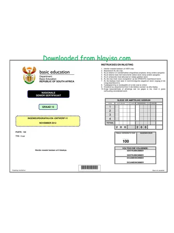



View all





Engineering Graphics and Design Grade 12 P1 2012 QP
Grade 12 Engineering Graphics and Design Paper 1 question paper from the NSC Supplementary 2012, 12 pages. Read online or download the free PDF.
Engineering Graphic And Design · Grade 12 · NSC Supplementary · 2012. Question paper, 12 pages. Read online or download the PDF.
- Subject
- Engineering Graphics and Design
- Grade
- Grade 12
- Document type
- Question paper
- Year
- 2012
- Exam period
- NSC Supplementary
- Paper
- 1
- Curriculum
- CAPS
- Pages
- 12
- File size
- 3.4 MB
Free to read online, no sign-up needed
Loading document…
Loading document…
1 of 12
This exam
NSC Supplementary 2012
- Paper 1Question paperMemo
- Paper 2Question paperMemo
Questions in this paper
Document textSearch extracted text and jump to a page.
Ingenieursgrafika en -ontwerp/V1t
Downloaded fram hlayiso.com
DBE/Feb.-Mrt. 2012
NOTA:
Kontrakteurs moet alle afmetings
en hoogtes
op die terrein bevestig voordat daar met werk
begin word. Argitekte moet onmiddellik in
kennis gestel word van enige afwyki
ings.
VRAAG 1: ANALITIES (SIVIEL)
Gegee:
‘n Gedetailleerde tekening van 'n snit deur die substruktuur van 'n nie-lasdraende
muur, die terreinplan vir 'n nuwe kompleks met 10 troshuise, 'n titelpaneel en 'n
tabel met vrae. Die tekene is nie volgens die aangetoonde skaal voorberei nie.
3 i Instruksies:
4 14. In die spasie hieronder, teken, in Voltooi die tabel hieronder deur die vrae, wat almal na die bygaande tekene en
[ netjiese vryhand, die vooraansig titelpaneel verwys, netjies te beantwoord. [30]
5. en boaansig van die SABS 0143-
——————* = konvensie vir 'n STORT
LET WEL:
DIE ARSERINGSBESONDERHEDE VRAAG ANTWOORD
IS UITGELAAT.
FONDASIE
6——_|_+
VOGWEERLAAG
GEDETAILLEERDE TEKENING VAN 'N SNIT DEUR DIE GRONDVLAK
SUBSTRUKTUUR VAN 'N NIE-LASDRAENDE MUUR BINNEMUUR
Met verwysing na die gedetailleerde tekening van 'n snit deur
4, | dle substruktuur van 'n nie-lasdraende muur, verbind dle BETONBLAD 10
nommer op die tekening met die korrekte komponent in die GEKOMPAKTEERDE
kolom regs van hierdie vraag. HARDEPUIN
ONGESTEURDE AARDE
RYLAAN ERF 27
AFGEWERK D 72000 | VLAKLAAG
ore I PLEISTER
KEISTENE |\\ | _ _ — 5000 BL _ _ _
i 6 [ARGITEK SE HANDTEKENING VOLTOOIDE VLOERVLAK
NI ERF 3 Se ee
tT Ng ° ALIENT SE HANDTEKENING 2. | Watis die verwysingskode van die tekening? 1
' \
! s 3. | Wie was verantwoordelik vir die druk van die terreinplan? 1
! ONTSPANNINGS-
nuwe, | | 4 | Wat is die afstand vanaf die boulyn na die palissadeheining? 1
ee 4 5 | in watter straat is die toegang tot die eiendom geleé? 1
y 6 | Wat word deur die kenmerk by 1 aangedui? 4
7 | Benoem die kenmerk by 2 1
I
z HERSIENING | DATUM | BESKRYWING | 8 | Benoem die kenmerk by 3. 1
3 NEW WAVE g | Benoem die kenmerk by 4. 1
8 ARCHITECTS 10 | Benoem die kenmerk by 5. 1
a 5S ARGILERYLAAN
z DURBAN 41 | Hoeveel geboue is op die erf? 4
2amHoe | & Tel: 031 303 8459 — - - -
aaa Wat is die opperviakafwerking van die rylane in die
' SEDRUKDEUR DRUOATUN 12 1
PALISSADE- ! kompleks?
VEILIGHEIDS- |_| ZAPPY DRUKKERS 2012-01-10
HEINING [1H TERENTTEL 413 | Bepaal die totale lengte van die metaalpalissade-velligheids- 3
1 TERREINPLAN heining in meter. Toon ALLE berekeninge.
J In die spasie voorsien in die titelpaneel, teken, in nefjiese
8 ou 14 | vryhand, die vooraansig en boaansig van die SABS 0143 3
rH konvensie vir 'n stort.
cnecncesod NUWE TROSBEHUISING VIR In die spasie hieronder, bepaal die totale opperviakte van 'n
DIE DUBE TRUST OP ERF 3 15 | gnkele eenheid in vierkante meter ia 3
7 TE STRELITZIARYLAAN 58 TOTAAL La
= — GINGINDLOVU. ANTWOORD 15 _ 40000
Y) (ELEKTRIESE \ ate sepriese tenks V7 (| Remwomer TEXENNGNOWNER Toon ALLE berekeninge. |
TOEVOER TERREINPLAN *"\woet vo.ceNs 18 02 2 g
KAAL 1: INGENIEUR- VERWVSNGSKODE GETEREN DER WAGESIEN DER | | ENKELE EENHEID | 3
Grensiences ) SKAAL 1: 200 SPESIFIKASIES GEBOU Q1Pt1-SUP-2012 | SANELE | LEBO oe EKSAMENNOMMER
AB=CD WORD. ‘DATUM, SKAAL 74000
— IMM — e
Kopiereg voorbehou mu il WU Blaai om asseblief
Downloaded fram hlayiso.com sche
VRAAG 2: ONTWIKKELING
Ingenieursgrafika en -ontwerpiV1
oe
Gegee:
Die vooraansig en boaansig van 'n gedeelte van ‘n kanaal
wat 'n vierkant-na-vierkant-oorgangstuk met twee verbinding-
stukke toon,
Instruksies:
2.1. Teken, volgens skal 1 : 1, die gegewe vooraansig en
boaansig van die gedeelte van die kanaal.
2.2 Ontwikkel die opperviak van SLEGS die oorgangstuk.
Maak sy AB die naat.
Toon ALLE nodige konstruksies en voulyne. [34]
VERBINDINGSTUK
OORGANGSTUK
cm ,
VERBINDINGSTUK
65
0
;
Es)
| H
50 b"
SY AB IS DIE NAAT.
ASSESSERINGSKRITERIA
VOORAANSIG +
1 BOAANSIG: "4
2 |WARELENGTE-METODE | 10
3 | ONTWIKKELING 13,
TOTAAL 34
EKSAMENNOMMER
HI TREE a
— Blaai om asseblief
Kopiereg voorbehou
Ingenieursgrafika en -ontwerp/V1t
Downloaded fram hlayiso.com
DBE/Feb.-Mrt. 2012
oe
VRAAG 3: PERSPEKTIEF
Gegee:
Twee aansigte van 'n kothuis en die inligting benodig om
‘n tweepuntperspektieftekening te teken.
PV - Prentvlak
HL - Horisonlyn
GL - Grondlyn
SP - Staanpunt
Instruksies:
Voltooi die perspektieftekening
© Rig die tekenvel volgens die grondlyn (GL).
* Toon ALLE nodige konstruksies.
* Toon die muurdikte by die deur en die vensters.
GEEN verborge besonderhede word verlang nie. [40]
PV PV
1
opottt
HL Lt HL
‘|
fou
PL!
'
GL ee J GL
ASSESSERINGSKRITERIA
KONSTRUKSIES + VP'e 7
TRAPPE 7
MURE + DEUR + VENSTERS. 17
+ DAK 9
SP TOTAAL 40
EKSAMENNOMMER
OI — i
Kopiereg voorbehou SU Blaai om asseblief
“enous eam Downloaded fram hlayiso.com secre usins
VRAAG 4; SIVIELE TEKENING
aes DAKKOMPONENTE 200 x 150 BETON- Gegee:
[2] [75x50 KAPLATTE STEUNBALK * Die onvolledige noord-oos-aansig van 'n nuwe kothuis wat
die mure, die posisie van die vensters, skuifdeur, die dak en
7 =
[—— [228 x 20 FASSIEPLANK / notas toon
108 eee 3 *Die onvolledige vioerplan wat die mure, posisie van die
W2 VENSTER 5 vensters, deure, toebehore en die elektriese toebehore toon
[= | 114 x 38 MUURPLAAT SKUIFDEUR * Daknotas en 'n skematiese diagram van 'n dakkap
VLOERVLAK *'n Diagram wat die kameraanduidings en vloerafwerkings
GRONDLYN \ QL _ toon
A
TOEBEHORE * Die onvolledige fondasie- en muurbesonderhede
ONVOLLEDIGE NOORD-OOS-AANSIG *'n Tabel met elektriese simbole
2 *'n Tabel met dakkomponente
® a *'n Tabel met toebehore
TORREHORE = —isé«iR WAP F-—7 «'n Deur- en vensterskedule ; ;
eee HORE eNIERDEUROPENINGE wi | Die onvolledige vioerplan van die nuwe kothuis, geteken
D2 SKUIFDEUROPENING owe J ]| | volgens skaal 1 : 50, op bladsy 6
es W1,W2_ VENSTEROPENINGE
Fa B BAD | Instruksies:
WB — OPWASBAK 4 | Beantwoord hierdie vraag op bladsy 6.
SSS sk TOILET *Deur die gegewe onvolledige vioerplan te gebruik, teken,
BAD (B) we IVASBAK ! | kaal 1: 50 en di fikasies, die volgend
x Bie INGEBOUDE KAS 3d volgens skaal 1: 50 en die spesifikasies, die volgende
- aansigte van die nuwe kothuis:
ELEKTRIESE TOEBEHORE = | 4.1 Die volledige vioerplan
7. DRIEPOOL-LIGSKAKELAAR ba | 4.2 Die noord-oos-aansig
2. ENKELPOOL-LIGSKAKELAARS ‘ .
3 PLAFONIIG jy | 4.3 'n Deursneeaansig volgens snyviak A-A
4.2.x 40 W FLUORESSEERBUISE Ww. I * ALLE tekene moet voldoen aan die riglyne en konvensies
5. SKAKELAARKRAGPUNT. URWAP Us DAKLYN, vervat in die SABS 0143.
LET WEL:
DIE PYL TOON DIE LIGVERBINDING ONVOLLEDIGE VLOERPLAN SPESIFIKASIES:
MET DIE SKAKELAAR AAN. DIE VLOERPLAN
Voeg die volgende kenmerke by die tekening:
DAKNOTAS: * AL die deure en vensters. Toon die oopmaakrigting van die
875 DAKBEDEKKING 15 mm GOLFYSTER- skuifdeur.
OPWASBAK (OWB) TOILET (Sk) WASBAK (WB) Poe? * 89 mm KAPLATTE @ * AL die toebehore soos aangedui deur die afkortings
*AL die elektriese toebehore soos aangedui deur die
' .
e 4114 x 38 mm DAKKAPPE OP 114 x 38 mm nommers
8 MUURPLATE | tS * AL die arseringsbesonderhede
OM TE PAS DAKHELLING 30° MET 228 x 20 mm - - -——>.
FASSIEPLANK AN BEIDE KANTE. | GELYK | cELYK PN DIE NOORD-OOS-AANSIG , -
INGEBOUDE KAS (BIC) fk x 1 Toon die volgende kenmerke op die tekening:
4100 mm VIERKANTBAKGEUT 200 © Die buitemure
SKEMATIESE DIAGRAM Di i i
DEUR: EN VENSTERSKEDULE GIPSPLAFONGORD OP 4 STROKE VAN MATIESE DIAGR ia Die dakbesonderhede, insluitend die geut, fassieplank en
1000 2000 $B.» 38 rm PLAFONCATTE. EWEREDIG pL———=. | _reénwaterafvoerpyp : ;
500 500 GESPASIEER «Die venster- en skuifdeurbesonderhede, insluitend al die
4 oopmaakrigtings
8 alg DIE DEURSNEEAANSIG
S 3 Toon die volgende kenmerke op die tekening:
~VENSTER UW! “| * Die volledige fondasie-, muur-, betonblad-, dak- en plafon-
uw ——] VLOERAFWERKING besonderhede
NOTA: 150 x 20 VESELSEMENTVENSTER- — VENSTER (W2) KOMBUIS: TEELS g * Die skuifdeurbesonderhede
BANK ONDER ALLE VENSTERS BADKAMER KOMBUIS SITKAMER: — TEELS. al * AL die arseringbesonderhede
OM TE PAS j QM TE PAS STOEP: TEELS :
+ rT 7 SITKAMER SLAAPKAMER: MAT Benoem die volgende:
BADKAMER: EELS * Die noord-oos-aansig en die deursneeaansig
PANEEL cusmomee a * Die kameraanduidings met vloerafwerkings ;
el | MAAK NA | sre pancen _ sroep Se * Deur die korrekte afkortings te gebruik, benoem die volgende
3} ||RecTeRKant si) of ff LL. ET GRONDVLAK 5; ——} 33 kenmerke op die korrekte aansig: grondvlak en vogweerlaag
oop S
KAMERAANDUIDINGS MET 8 CO — at LET WEL:
VLOERAFWERKINGS: 700 & « ALLE substruktuurarsering mag in vryhand geteken word.
_ (96)
SKUIFDEUR EN RAAM (02) DEUR EN RAAM (D) ONVOLLEDIGE FONDASIE- EN {96]
i — z
“enous eam Downloaded fram hlayiso.com secre usine
ASSESSERINGSKRITERIA
VLOERPLAN
1 [evsxerre 5
2 [evextres 8
4 | toescHoRe 6
A 5 | Venstes 12
hv RWAP nT oO 7 6 | arsenic 6
1 2 | SUBTOTAAL | 37
| N | NOORD-00S-AANSIG
| ‘ \ | 1 | Mure + vw 4
\ + GEUTe
\ Ran &
! ;
\ .
| \ | 3 |ocur 9
Lon
| N | 4 | BySKRIFTE 4
| |
| ee +-—4 SUBTOTAAL 21
| _ | DEURSNEEAANSIG
| |
4 | DAK 13
| |
| \— Cc | 2 [Mowonses | 152
| | 3 | skUIFOEUR 1
| |
| | 4 | syskriFTe 13
| J ee PL — | 5 | ARSERING 7
| YO | SUBTOTAAL 38
7 RWAP
yet DAKLYN | TOTAAL 96
PLAN A EKSAMENNOMMER
SKAAL 1 : 50
i —_
Downloaded from hlayiso.com
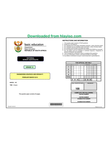
INSTRUCTIONS AND INFORMATION
1. This question paper consists of FOUR questions.
2. Answer ALL the questions.
3. ALL drawings are in first-angle orthographic projection, unless otherwise stated.
4. ALL drawings must be completed using instruments, unless otherwise stated.
5. ALL answers must be drawn accurately and neatly.
6. ALL the questions must be answered on the QUESTION PAPER as instructed.
7. ALL the pages must be re-stapled in numerical sequence, irrespective of
whether the question was attempted.
8. Time management is essential in order to complete all the questions.
9. Print your examination number in the block provided on every page.
10. Any details or dimensions not given must be assumed in good proportion.
NATIONAL
SENIOR CERTIFICATE
FOR OFFICIAL USE ONLY
QUESTION MARKS OBTAINED ½ SIGN MODERATED ½ SIGN
GRADE 12 1
2
3
ENGINEERING GRAPHICS AND DESIGN P1 4
FEBRUARY/MARCH 2012 TOTAL
2 0 0 2 0 0
MARKS: 100
FINAL CONVERTED MARK CHECKED BY
TIME: 3 hours
_______
100
COMPLETE THE FOLLOWING:
This question paper consists of 6 pages. CENTRE NUMBER
CENTRE NUMBER
EXAMINATION NUMBER
EXAMINATION NUMBER
!GAUTENG!
Copyright reserved
Please turn over
Engineering Graphics and Design/P1
Downloaded from hlayiso.com
DBE)
Feb -Mar. 2012
NOTE:
DRIVEWAYS
FINISHED
WITH
COBBLE
STONES,
NEW
INDIGENOUS:
TREES ~
2,3 m HIGH
METAL
PALISADE
SECURITY
THE HATCHING DETAIL
HAS BEEN OMITTED,
DETAILED DRAWING OF A SECTION THROUGH THE
SUBSTRUCTURE OF A NON-LOAD-BEARING WALL
STAND 27 |
72000 44000
— 5000 BL _ _ =
STAND 3 e es
6 @'
RECREATIONAL
121000
FENCE
SECURITY
CONTROL
BUILDING
®
5000 BL.
NOTE:
Contractors must verify all dimensions and
levels on site before commencing work.
Architects to be immediately notified of any
discrepancies.
14. In the space below, draw, in neat
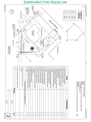
QUESTION 1: ANALYTICAL (CIVIL)
Given:
A detailed drawing of a section through the substructure of a non-load-bearing
wall, the site plan for a new complex with 10 cluster homes, a title panel and a
table of questions. The drawings have not been prepared to the indicated scale
Instructions:
Complete the table below by neatly answering the questions, which all refer to
i NEE { EE
/—-MAINROAD ~;
(ELECTRICAL
‘SUPPLY
ES95
BOUNDARY LENGTHS
‘AB=CD
SITE PLAN
SCALE 1 : 200
ALL SEPTIC TANKS
TO BE BUILT TO
ENGINEER'S
‘SPECIFICATIONS
AD =BC
freehand, the front view and top the accompanying drawings and title panel. 30)
ying 9
view of the SABS 0143
convention for a SHOWER. QUESTIONS ANSWERS
FOUNDATION
DAMP-PROOF COURSE
GROUND LEVEL
. . INTERNAL WALL
With reference to the detailed drawing of a section through
4, | the substructure of a non-load-bearing wall, link the number | CONCRETE SLAB 10
on the drawing with the correct component in the column to | GoMPACTED HARDCORE
the right of this question.
UNDISTURBED EARTH
SCREED
PLASTER
FINISHED FLOOR LEVEL
ARCHITECTS SIGNATURE
2 | Whatis the reference code for the drawing? 1
CLIENTS SIGNATURE —
3. | Who was responsible for the printing of the site plan? 1
4, | What is the distance from the building line to the palisade 4
fence?
5 | Inwhich road is the access to the property located? 1
6 | What does the feature at 1 indicate? 1
7 | Name the feature at 2. 1
REVISION pate | vescription | 8 |Name the feature at 3. 1
NEW WAVE 9 | Name the feature at 4 1
ARCHITECTS 10 | Name the feature at 5. 1
a AOUREAN 11 | How many buildings are on the stand? 1
Tel: 031 303 8459
12 | Whats the surface finish of the driveways in the complex? 1
PRINTED EY DATE OF PRINT
ZAPPY PRINTERS 2012-01-10 43 | Determine the total length of the metal palisade security 3
DRAWING THLE fence line in metres. Show ALL calculations.
SITE PLAN In the space provided in the title panel, draw, in neat
14 | freehand, the front view and top view of the SABS 0143 3
ROner convention for a shower.
NEW CLUSTER HOMES FOR 45 | Inthe space below, determine the total area of a single unit in 3
DUBE TRUST ON STAND 3 AT Square metres
58 STRELITZIA ROAD ANSWER 15
GINGINDLOVU. Show ALL calculations. ¢—t0000__y TOTAL | 30
PROJECT NOWBER DRAWING NUMBER ——
18 002-8 2
REFERENCE CODE DRAWNBY [CHECKED BY 8) | SINGLE UNIT 3
Q1P1-SUP-2012 | SANELE | LEBO ° EXAMINATION NUMBER
DATE SOA T4000
2011-02-30) 1: 200 EXAMINATION NUMBER [ 2
Copyright reserved
Won
Please tum over
DBE/Feb.-Mar. 2012
nn Downloaded from hlayiso.com
QUESTION 2: DEVELOPMENT
Given:
The front view and top view of a portion of a duct showing a
square-to-square transition piece with two connecting
pieces.
Instructions:
2.1 Draw, to scale 1: 1, the given front view and top view
of the portion of the duct.
2.2 Develop the surface of the transition piece ONLY.
Make edge AB the seam.
Show ALL necessary construction and fold lines. [34]
CONNECTING PIECE
TRANSITION PIECE
65.
FY
CONNECTING PIECE
EDGE AB IS THE SEAM
ASSESSMENT CRITERIA
FRONT VIEW + TOP
VIEW
11
2) TRUE LENGTH METHOD | 10
3 | DEVELOPMENT 13,
TOTAL 34
EXAMINATION NUMBER
HI anamaTonnower [5
— Please tum over
Copyright reserved
Engineering Graphics and Design/P1
Downloaded from hlayiso.com —
QUESTION 3: PERSPECTIVE
Given:
Two views of a cottage and the information needed to
draw a two-point perspective drawing
PP ~ Picture plane
HL - Horizon line
GL - Ground line
SP - Station point
Instructions:
Complete the perspective drawing
* Align the drawing sheet with the ground line (GL)
© Show ALL necessary construction
© Show the wall thickness at the door and the windows.
« NO hidden detail is required. [40]
PP. PP
opottt
HL Lt HL
+
mee
Pi
|
GL t---------| ! cc
ASSESSMENT CRITERIA
4 | CONSTRUCTION + VPs 7
2 | STAIRS 7
3 WINDOWS 17
+ 4 | ROOF 9
SP TOTAL 40
EXAMINATION NUMBER
EXAMINATION NUMBER [4
Copyright reserved
Won
Please tum over
Engineering Graphics and Design/P1
Downloaded from hlayiso.com
DBE/Feb.-Mar. 2012
ELECTRICAL ROOF COMPONENTS
SXMEOES: 75 x 50 PURLINS
[——1 |228 x 20 FASCIA BOARD.
114 x 38 WALL PLATE
FIXTURES,
200 x 150 CONCRETE
SUPPORT BEAM
100 x 100 BOX GUTTER
100 mm RWOP
W2 WINDOW
2100
SLIDING DOOR
FLOOR LEVEL
GROUND LINE
FIXTURES
D1 HINGED DOOR OPENINGS
2 SLIDING DOOR OPENING
W1, W2_ WINDOW OPENINGS
B BATH
s SINK
we TOILET
WB WASHBASIN
BIC BUILT-IN CUPBOARD
ELECTRICAL FIXTURES
400
a
WASHBASIN (WB)
875
SINK (S)
TOILET (WC)
TO FIT
BUILT-IN CUPBOARD (BIC)
DOOR AND WINDOW SCHEDULE
4000 2000
500 500
1. THREE-POLE LIGHT SWITCH
2. SINGLE-POLE LIGHT SWITCHES,
3. CEILING LIGHT
4.2x 40 W FLUORESCENT TUBES.
5. SWITCH SOCKET OUTLETS,
NOTE:
THE ARROW SHOWS THE LIGHT
CONNECTION TO THE SWITCH.
ROOF NOTES:
ROOF COVER 15 mm CORRUGATED
IRON ON 75 x 50 mm PURLINS @
1450 cle.
114 x 38 mm ROOF TRUSSES ON
114 x 38 mm WALL PLATES.
ROOF PITCH 30° WITH 228 x 20 mm
FASCIA BOARD ON BOTH ENDS.
100 mm SQUARE BOX GUTTER
PLASTER CEILING BOARD ON 4
STRIPS OF 38 x 38 mm BRANDERING,
EVENLY SPACED
\
INCOMPLETE NORTH-EAST ELEVATION
ROOF LINE
INCOMPLETE FLOOR PLAN
va EQUAL
KITCHEN
SLIDING DOOR AND FRAME (02) DOOR AND FRAME (D)
LOUNGE
=) FLOOR FINISH
KITCHEN: — TILES
LOUNGE: TILES
PORCH: TILES
BEDROOM: CARPET
BATHROOM: TILES
WINDOW (W1)
NOTE: 150 x 20 FIBRE CEMENT WINDOW nD
SILL UNDER ALL WINDOWS. (2) BATHROOM
' To FIT j Horn,
PANEL BEDROOM
8} |] rowars || FIXED PANEL 8
SJ || THE RIGHT Ny
ROOM DESIGNATIONS
WITH FLOOR FINISH
Copyright reserved
Won
t ben
SCHEMATIC DIAGRAM
OF A ROOF TRUSS: 200
pu =
al
==,
GROUND wey | 2B
“ 700__| —
INCOMPLETE FOUNDATION
AND WALL DETAIL
QUESTION 4: CIVIL DRAWING
Given:
The incomplete north-east elevation of a new cottage
showing the walls, the position of the windows, sliding door,
the roof and notes
«The incomplete floor plan showing the walls, position of the
windows, doors, fixtures and the electrical fixtures
Roof notes and a schematic diagram of a roof truss
* A diagram showing the room designations and floor finishes
« The incomplete foundation and wall detail
© A table of electrical symbols
© A table of roof components
© A table of fixtures
* A door and window schedule
The incomplete floor plan of the new cottage, drawn to
scale 1: 50, on page 6
Instructions:
* Answer this question on page 6.
* Using the given incomplete floor plan, draw, to scale 1: 50
and to the specifications, the following views of the new
cottage:
4.1 The complete floor plan
4.2 The north-east elevation
4.3 A sectional elevation on cutting plane A-A
*ALL drawings must comply with the guidelines and
conventions contained in the SABS 0143.
SPECIFICATIONS:
THE FLOOR PLAN
Add the following features to the drawing:
ALL doors and windows. Show the direction of opening for
the sliding door.
* ALL fixtures as indicated by the abbreviations
* ALL the electrical fixtures as indicated by the numbers
* ALL hatching detail
THE NORTH-EAST ELEVATION
Show the following features on the drawing:
© The outside walls
*The roof detail including the gutter, fascia board and
rainwater downpipe
The window and sliding door detail including all the
directions of opening
THE SECTIONAL ELEVATION
Show the following features on the drawing:
* The complete foundation, wall, slab, roof and ceiling detail
* The sliding door detail
* ALL hatching detail
Label the following:
* The north-east elevation and the sectional elevation
* The room designations with floor finishes
* Using the correct abbreviations, label the following features
in the correct view: ground level and damp-proof course.
NOTE:
* ALL substructure hatching may be drawn in freehand. [96]
Bl
Please tum over
Engineering Graphics and Design/P1
Downloaded from hlayiso.com
DBE/Feb.-Mar. 2012
|
| \ RWDP |
; Se
1 [PS |
~
| \ |
| \. |
| |
| |
| |
| |
| }————-—-----~-------4 +—4
| |
| S| |
| |
| _l C}
| |
| |
i ee —4 |
1 U6 |
| _/ RWDP |
wot ROOF LUNE | __
PLAN
SCALE 1 : 50
Copyright reserved
Won
ASSESSMENT CRITERIA
FLOOR PLAN
LABELS 5
ELECTRICAL 8
FITTINGS, 6
wnbows 12
HATCHING 6
SUBTOTAL 37
NORTH-EAST ELEVATION
WALLS “FFL 4
Gurrer+ rior | 92
wnpons+ 9
LaseLs iH
SUBTOTAL 21
SECTIONAL ELEVATION
ROOF 13
WALLS + FLOOR 4
+rounoarions | 153
SLIONG DOOR 1
LABELS 1h
HATCHING 7
‘SUBTOTAL 38
TOTAL 96
EXAMINATION NUMBER
EXAMINATION NUMBER
Study this subject
Recommended for this subject
Question paper
Engineering Graphics and Design Grade 12 P1 2012 QP (Afr)
Question paper
Engineering Graphics and Design Grade 12 P1 2013 QP (Eng)
Memorandum
Engineering Graphics and Design Grade 12 P2 2012 Memo
Memorandum
Engineering Graphics and Design Grade 12 P1 2012 Memo
Memorandum
Engineering Graphics and Design Grade 12 P1 2013 Memo (Eng)
Question paper
Engineering Graphics and Design Grade 12 2012 QP
More from Grade 12 Engineering Graphics and Design
Memorandum
Engineering Graphics and Design Grade 12 P1 2025 Memo
Memorandum
Engineering Graphics and Design Grade 12 P2 2025 Memo (Eng)
Memorandum
Engineering Graphics and Design Grade 12 P2 2025 Memo
Memorandum
Engineering Graphics and Design Grade 12 P2 2024 Memo (Eng)
Memorandum
Engineering Graphics and Design Grade 12 P1 2023 Memo (Afr)
Question paper