
INSTRUCTIONS AND INFORMATION
1. The question paper consists of FOUR questions.
2. Answer ALL the questions.
3. ALL drawings must be drawn to scale 1 : 1, unless otherwise stated.
4. ALL questions must be answered on the answer sheets provided.
5. ALL the answer sheets must be re-stapled in numerical sequence and
handed in irrespective of whether the question was attempted or not.
6. Careful time management is essential in order to complete all the questions.
7. Print your name in the block provided on EVERY ANSWER SHEET.
ISEBE LEMFUNDO LEMPUMA KOLONI 8. ALL answers must be drawn accurately and neatly.
EASTERN CAPE EDUCATION DEPARTMENT 9. Any details or dimensions not given must be estimated in good proportion.
OOS-KAAP ONDERWYSDEPARTEMENT 10. ALL drawings are in third angle orthographic projection, unless otherwise
stated.
FOR OFFICIAL USE ONLY
MODERATED
NATIONAL SENIOR CERTIFICATE MARK
1
2
3
4
GRADE 11 TOTAL
2 0 0 2 0 0
FINAL CONVERTED CHECKED BY
MARK
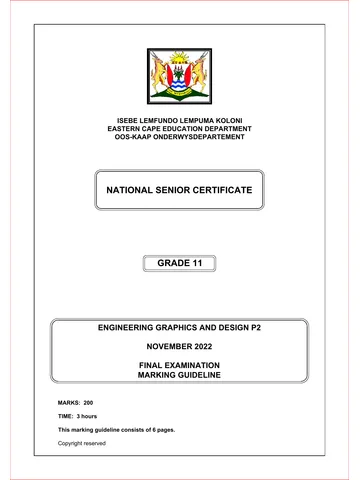
ENGINEERING GRAPHICS AND DESIGN P2
NOVEMBER 2022
100
FINAL EXAMINATION COMPLETE THE FOLLOWING:
NAME
NAME
MARKS: 200
EXAMINATION CENTRE
TIME: 3 hours
This question paper consists of 6 pages.
SCHOOL
Copyright reserved
Please turn over 1
Skip to contentQuestion paper 
View all
Engineering Graphic And Design Grade 11 P2 2022 QP (Eng)
Grade 11 Engineering Graphic And Design Paper 2 question paper from the Exemplar November Exam 2022 (English), 6 pages. Read online or get the free PDF download, memo linked when available.
Engineering Graphic And Design · Grade 11 · Exemplar November Exam · 2022 · English. Question paper, 6 pages. Read online or download the PDF.
- Subject
- Engineering Graphic And Design
- Grade
- Grade 11
- Language
- English
- Document type
- Question paper
- Year
- 2022
- Exam period
- Exemplar November Exam
- Paper
- 2
- Curriculum
- CAPS
- Pages
- 6
- File size
- 970.2 KB
Loading document…
Loading document…
1 of 6
Document textSearch extracted text and jump to a page.
Engineering graphics and design / P2 NSC EC / November 2022
LE
VIEW 1 QUESTION 1: ANALYTICAL (MECHANICAL)
AP
ST
Given:
A detailed drawing of a honing device, a title block, assembled views, isometric view and a table of questions. The drawings
have not been prepared to the indicated scale.
Instructions:
Complete the table below by neatly answering the questions, which all refer to the accompanying drawings and the title block.
[32]
QUESTIONS ANSWERS
A
MAX. DISTANCE 80 MM 1 What is the title of the drawing? 1
VIEW 2 VIEW 3
2 What is the shop number? 1
3 What is the file name? 1
ISOMETRIC VIEW 4 On what date was the drawing drawn? 1
5 Who checked the drawing? 1
MIN. DISTANCE 6 MM
SCALE 2:1 6 Who approved the drawing? 1
20 10
15 8 2 7 Which drawing program was used? 1
M6
8 How many parts make up the honing device? 1
v
9 How many axles must be manufactured? 2
24 34 y 10 How many revisions were there? 1
11 What is VIEW 1 called? 1
2 3
13
5 12 What is VIEW 2 called? 1
R7
M12 30° What is the maximum chisel width, in centimetres, that can be sharpened
R4 R5 13 2
M8 with the honing device?
u GRUB SCREW (7)
26 14 What is the purpose of the grub screw? 2
13 4 R5 R7
9
4 15 Name the feature at A. 1
w 15 2 2
u 1
16
5
SLIDE (1)
17
BASE (2) v 1
45° x 16 Determine the complete dimensions and/or degrees at: w 1
45° Ø16 x 1
5 M6 Ø16
y 2
12
17 In the space below (ANSWER 17), draw, in neat freehand, the conventional method of the RIGHT section of the given ball bearing. 4
M12
Ø14 WASHER (8)
18 KEEPS WHEEL IN CENTER 18 In the space below (ANSWER 18), draw, in neat freehand, the SANS symbol for the projection system used. 4
17 Ø12
20
18
TOTAL 32
PARTS LIST
CROSSWAYS
ANSWER 17
KNOB (3) WHEEL (4) Ø6 GREAT KEI VILLAGE CENTRE
SHOP 11
3 M12 TOOL MAKERS KWELERA 5259
PART QUANTITY MATERIAL ' 043 355 2274
7 5
1. SLIDE 1 CAST IRON TITLE:
2. BASE 1 CAST IRON
HONING DEVICE
3. KNOB 1 ALUMINUM 1. CHECK SCALE 2021/03/19 ANSWER 18
69 M8 88
4. WHEEL 1 COPPER 2. SHOW KNURLING ON KNOB 2021/03/20
AXLE (5) THREADED AXLE (6)
5. AXLE 2 STEEL 3.
6. THREADED AXLE 1 STEEL 4.
QUANTITY: 11 000 FINISH: 7. GRUB SCREW 1 STEEL
ALL DIMENSIONS ARE IN REVISIONS DATE
SCALE 1:1
MILLIMETRES. DRAWING NO.: HD 501
0.05
MACHINED 8. WASHER 2 STEEL NAME
FILE NAME: hd207b.dwg SURNAME DATE SURNAME DATE SURNAME DATE
ALL UNDIMENSIONED RADII ARE R3. C
PROGRAM: AUTOCAD 2021 DRAWN VAN WYK 2021/03/15 CHECKED NAIKER 2021/03/20 APPROVED FAKU 2021/03/28 NAME 2
Copyright reserved Please turn over
Engineering graphics and design / P2 NSC EC / November 2022
LE QUESTION 2: CAM
AP
ST
Given:
· The detail of a camshaft and a follower in its lowest
position.
· The vertical centre line of the cam profile.
Specifications:
· The follower reciprocates on the vertical centre line of
the camshaft.
· Minimum distance from the cam profile to the centre of
the camshaft = 22 mm.
· Rotation = clockwise
Motion:
The cam imparts the following motion to the follower:
· It rises 24 mm with uniform motion over the first 60°.
· There is a dwell period for the next 90°.
· It rises 26 mm with uniform motion over the next 60°.
· There is a dwell period for the next 60°.
· It returns to the original position with uniform motion
over the rest of the rotation.
Instructions:
· Draw, to scale 1 : 1, the given camshaft and the
wedge-shaped follower detail at its minimum position.
· Show the direction of rotation on the cam profile.
· Draw to a rotational scale of 360° = 120 mm and a
displacement scale of 1 : 1, the complete displacement
graph for the required motion.
· Label the displacement graph and include the scale.
· Project and draw the cam profile that would generate the
given motion.
· Show ALL necessary constructions and projections. [37]
10 ASSESSMENT CRITERIA
1 GIVEN + MIN. DISTANCE 5½
2 GRAPH CONSTRUCTION 3
57 UNIFORM MOTION +
60° 3 6½
DWELL
4 GRAPH LABEL + SCALE 2
5 CAM CONSTRUCTION 10
22
6 CAM + CURVE QUALITY 10
Ø20 TOTAL 37
NAME
NAME 3
Copyright reserved Please turn over
Engineering graphics and design / P2 NSC EC / November 2022
LE QUESTION 3: ISOMETRIC DRAWING
AP
ST
Given:
· The front view, top view and left view of a paper weight.
· The position of point S on the drawing sheet.
Instructions:
Using scale 1 : 1, convert the orthographic views of the paper weight into an
isometric drawing.
· Make S the lowest point of the drawing.
· Show ALL necessary construction.
· NO hidden detail is required. [44]
100
40
20
28
40
40
S
50
R50
20 40
20
R30
80
20
10
60 S S 20 5 20
100
ASSESSMENT CRITERIA
1 AUX' VIEW + PLACING 3
2 ISOMETRIC LINES 22
3 NON-ISOMETRIC LINES 5
S 4 HEXAGON + SQUARE 4½
CIRCLE +
5 CIRCLE CONST.
7½
6 CENTRE LINES 2
TOTAL 44
NAME
NAME 4
Copyright reserved Please turn over
Engineering graphics and design / P2 NSC EC / November 2022
AP
LE 6 QUESTION 4: MECHANICAL ASSEMBLY
ST
9 4 Given:
6 · Orthographic views of each of the parts of a chain pulley
2 assembly.
5 9
· The exploded isometric drawing of the parts of a chain
pulley assembly, showing the position of each part
3 22 30 5 relative to all the others.
· The incomplete half-sectional front view and the
11 centerlines of the pulley in the left view on page 6.
55 M20 Instructions:
11 · Answer this question on page 6.
10 · Draw, to scale 1 : 1 and in third-angle orthographic
60 110
5 10 projection, the following view of the assembled parts of
Ø44
A the chain pulley assembly:
2 4.1 The half-sectional front view on cutting plane
A-A of the assembly as seen from the direction of the
10
arrow on the exploded isometric drawing.
1
9 80
Show the left half in section.
The cutting plane is shown on the top view of the
7 32 A
5
base (part 1).
4.2 The left view
3
6 20
40 NOTE:
V IEW · Planning of the layout of the views is essential.
10 O NT
FR · All drawings must comply with the guidelines as
4 Ø20 contained in the SANS 10111.
9 160 · Show, in the half-sectional front view, THREE faces of
6 50 the M20 bolt.
8 25 BASE [1] · Draw the section of the roller-bearing according to the
Ø22 conventional method.
Ø10
10 · Show all constructions.
20 ° Ø114 Ø22 3 24 20 3
75 · NO hidden detail is required. [87]
M8
21 Ø16
20 10
90 Ø16
15 3 3
30 9 9
Ø100 PARTS LIST
Ø30 Ø58
62
Ø80
PART MATERIAL QUANTITY
AXLE X 2 [4]
10 1. BASE CAST IRON 1
R2 12 Ø30 2. BRACE STEEL 2
40
20 3. PULLEY CAST IRON 2
Ø20 15 Ø36
Ø23 4. AXLE STEEL 2
20 60
5 5. ROLLER BEARING STEEL 2
12 100 Ø16
20 6. M8 SCREW MS 4
40 2
7. LEFT SIDE AXLE HOLDER CAST IRON 2
BRACE X 2 [2] PULLEY X 2 [3] ROLLER BEARING X 2 [5]
8. RIGHT SIDE AXLE HOLDER CAST IRON 2
9. M20 BOLT MS 4
17 3 3 17
4 10. M20 WASHER MS 4
23 Ø20
3 R9 R9 11. CIRCLIP MS 2
M8 20 20 Ø4 7 3
2 33 33
Ø12 Ø8 TITLE:
4 4
M20
2 11
16
8
16
8 13 CHAIN PULLEY
Ø12 4 4 Ø12 Ø40
4
GREAT KEI CROSSWAYS VILLAGE CENTRE
SHOP 11
14 30 30 14 36 R5 R9 KWELERA 5259
9 Ø8 9 TOOL MAKERS ' 043 355 2274
M8 SCREW X 4 [6] LEFT BRACE X 2 [7] RIGHT BRACE X 2 [8] M20 BOLT X 4 [9] M20 WASHER X 4 [10] CIRCLIP X 2 [11] ALL DIMENSIONS ARE METRIC.
ALL UNDIMENSIONED RADII ARE R5.
5
Copyright reserved Please turn over
Engineering graphics and design / P2 NSC EC / November 2022
LE
AP
ST
ASSESSMENT CRITERIA
LEFT VIEW
1 BASE 3
2 BRACES 3
3 PULLEYS 1½
4 AXLES 1
5 AXLE HOLDERS 3½
6 M20 BOLTS AND WASHER 7
7 M8 SCREWS 5
SUB-TOTAL 24
HALF SECTIONAL FRONT VIEW
1 BASE 5
2 BRACES 3
3 PULLEYS 17
4 AXLES 13½
5 ROLLER BEARING 4
6 AXLE HOLDERS 4
7 M20 BOLT 7½
8 M20 WASHER 2
9 CIRCLIP 3
10 ASSEMBLY 4
SUB-TOTAL 63
PENALTIES (-)
TOTAL
NAME
NAME 6
Copyright reserved
Matching paper and memo
The question paper, memo or addendum that belongs with this document.
Study this subject
Revise the topics in this paper, then practise them question by question.
- Grade 11 Engineering Graphics And Design notes
CAPS revision notes with worked examples.
- Engineering Graphics And Design questions by topic
Past exam questions sorted by CAPS topic, with memos where available.
- Grade 11 past papers
More Engineering Graphic And Design and other subjects in this collection.
Recommended for this subject
More papers and memos for this grade and subject.
Question paper
Engineering Graphic And Design Grade 11 P1 2022 QP (Eng)
Question paper
Engineering Graphic And Design Grade 11 P2 2022 QP (Eng)
Question paper
Engineering Graphic And Design Grade 11 P1 2022 QP (Eng)
Question paper
Engineering Graphic And Design Grade 11 2020 QP
Question paper
Engineering Graphic And Design Grade 11 2020 QP
Question paper
Engineering Graphic And Design Grade 11 P1 2020 QP
Related documents
Memorandum
Engineering Graphic And Design Grade 11 P1 2022 Memo (Eng)
Memorandum
Engineering Graphic And Design Grade 11 P2 2022 Memo (Eng)
Question paper
Engineering Graphic And Design Grade 11 P1 2020 QP (Eng)
Question paper
Engineering Graphic And Design Grade 11 P2 2020 QP
Question paper
Engineering Graphic And Design Grade 11 P2 2020 QP
Question paper
Engineering Graphic And Design Grade 11 P2 2019 QP
More from Grade 11 Engineering Graphic And Design
Annual teaching plan
Gr 11 EngGraph Des ATP 2023 24
Memorandum
Engineering Graphic And Design Grade 11 P1 2022 Memo
Memorandum
Engineering Graphic And Design Grade 11 P1 2020 Memo
Memorandum
Engineering Graphic And Design Grade 11 P1 2020 Memo
Memorandum
Engineering Graphic And Design Grade 11 P1 2020 Memo
Memorandum