
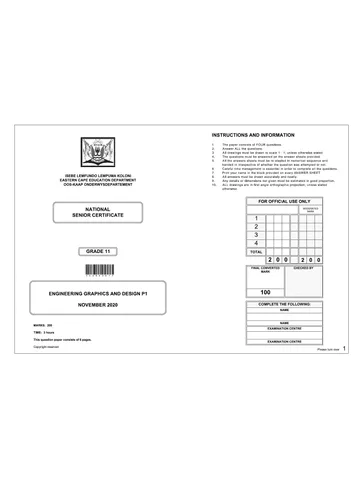
ISEBE LEMFUNDO LEMPUMA KOLONI
EASTERN CAPE EDUCATION DEPARTMENT
OOS-KAAP ONDERWYSDEPARTEMENT
NATIONAL
SENIOR CERTIFICATE
*IGRDSET*
>
ENGINEERING GRAPHICS AND DESIGN P1
NOVEMBER 2020
MARKS: 200
TIME: 3 hours
This question paper consists of 6 pages.
Copyright reserved
INSTRUCTIONS AND INFORMATION
The paper consists of FOUR questions
Answer ALL the questions
All drawings must be drawn to scale 1 : 1, unless otherwise stated
The questions must be answered on the answer sheets provided
All the answers sheets must be re-stapled in numerical sequence and
handed in irrespective of whether the question was attempted or not.
Careful time management is essential in order to complete all the questions.
Print your name in the block provided on every ANSWER SHEET.
All answers must be drawn accurately and neatly.
Any details or dimensions not given must be estimated in good proportion
0. ALL drawings are in first angle orthographic projection, unless stated
otherwise
ORONS
2 Oana
FOR OFFICIAL USE ONLY
MODERATED
MARK
oa
TOTAL
2/0/0 2/0/0
FINAL CONVERTED CHECKED BY
MARK
100
COMPLETE THE FOLLOWING:
NAME
NAME
EXAMINATION CENTRE
EXAMINATION CENTRE
Please turn over 1
Skip to contentQuestion paper 
View all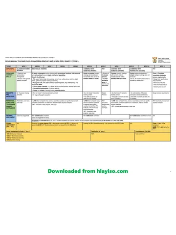
Engineering Graphic And Design Grade 11 P1 2020 QP (Eng)
Grade 11 Engineering Graphic And Design Paper 1 question paper from the National Exemplar November Exam 2020 (English), 6 pages. Read online or get the free PDF download, memo linked when available.
Engineering Graphic And Design · Grade 11 · National Exemplar November Exam · 2020 · English. Question paper, 6 pages. Read online or download the PDF.
- Subject
- Engineering Graphic And Design
- Grade
- Grade 11
- Language
- English
- Document type
- Question paper
- Year
- 2020
- Exam period
- National Exemplar November Exam
- Paper
- 1
- Curriculum
- CAPS
- Pages
- 6
- File size
- 1010.9 KB
Loading document…
Loading document…
1 of 6
Document textSearch extracted text and jump to a page.
Engineering graphics and design / P1
NSC
EC / November 2020
INCOMPLETE FLOOR PLAN
900
a 5 500
(j,LZZZZZ
BEDROOM
CARPET
17,48 mi?
c
gs BATHROO!
S| PASSAGE TILES
2 TILES 7,03 m?
2,48 mt
A—*
LOUNGE / DINING ROOM
woop
17,59 m? II
Ll II
im KITCHEN
B 1 | TILES
4 in 5,95 m*
a“ i
2
§| 8 I
a
7] A] @
Ot)
NOTE:
QUESTION 1A: ANALYTICAL (CIVIL)
Given:
The incomplete floor plan of a house. A title panel and a table of questions. The drawing has not been prepared to
an indicated scale.
Instructions:
Complete the table below by neatly answering the questions, which refer to the accompanying drawing and title
Contractors must verify all dimensions panel. [28]
and levels on site before commencing
work. Architects to be notified
immediately of any dsorepancies QUESTIONS ANSWERS
1 | What is the name of the architectural firm responsible for
ARCHITECTS SIGNATURE 1
drawing the house plans?
CUENTS SIGNATURE 2 | Whatis the project number for this drawing? 1
3 | 2020-08-27 |conmtere tHe wnoows 3 | Who was the person responsible for checking the 1
correctness of the drawing?
2 2020-03-27,
INSERT THE Door’ 4 | Whois the person responsible for drawing the floor plan? 1
1 | 2020-03-27 |THE FLOORPLAN
5 | When was the drawing printed?
REVISION DATE DESCRIPTION 1
6 | Who is the owner of the house?
BOTHA ARCHITECTS 1
11 Da Gamma street ——
2
JEFEREYSEAY 7 | What feature is indicated by the symbol at A’ 1
6330
TEL: 072 293 0392 8 | What feature does the line, indicated by arrow B show? a
FAX: 042 293 0392
EMAIL; kbotha@gmail,com - - -
SENT OME OF PART 9 | What does the abbreviation NTS in the tle panel stand 1
BLUEDEVILLE 2020-04-01 for!
10 | Has revision 3 been done correctly? Explain
DRAWNG THLE 1
FLOOR PLAN
ORG 14 | What is wrong with the hatching in the floor plan? 5
PROPOSED NEW HOUSE FOR
MRS. X. RUPPING, STAND 1442, 12 | What does the abbreviation BIC indicate?
THORNHILL, EASTERN CAPE. 2
Sa EE 18 | Which VIEW is indicated by arrow C? a
DP 2020 - 04 ofa
DATE [DRAWN |@REOKED | SCALE 14 | What is the width of the doors in mm if a scale of 1 : 100
2020 -03- 20} LINDO TYRON NTS: was used? a
ee 0E.2020 15 | In the space provided below, determine the perimeter of the entire house y
16 | In the space provided below, determine the total floor area that must be tiled, in square meters. | 4
TOTAL | 27
ANSWER 15 ANSWER 16
NAME
NAME [2
Copyright reserved
Please tum over
Engineering graphics and design / P1
NSC
EC / November 2020
QUESTION 2: INTERPENETRATION AND DEVELOPMENT
Given:
The top view and incomplete front view of a right regular
triangular prism that penetrates a right regular hexagonal
prism
The auxiliary view of the triangular prism:
The position of point X, the centre ofthe hexagon and starting
point for the top view.
A starting point AB for the development required.
Instructions:
Draw, to a scale 1 : 1 and in first angle orthographic projection, the
following views of the two solids:
24
2.2
2.3
24
The given top view using point X as a starting point.
The complete front view showing the curve of interpenetration.
The left view
The surface development of the triangular prism.
Use line AB as reference point.
Show ALL constructions.
[39]
B
3
ES)
4o__| 3
°
g
3
s
50 |
ASSESSMENT CRITERIA
4 | TOP view = G
CONSTRUCTION
2 FRONT VIEW + 9
INTERPENETRATION
3] LeFT view 8
4) DeveLOPMENT 16
TOTAL | 39
A
NAME
NAME [3
Copyright reserved
Please tum over
Engineering graphics and design / P1
NSC
EC / November 2020
QUESTION 3: PERSPECTIVE
Given:
Two views of a HOUSE and the information needed
to draw a two-point perspective drawing.
PP - Picture plane
HL - Horizon line
GL ~ Ground line
SP - Station point
Instructions:
Complete the perspective drawing
* Align the drawing sheet with the ground line (GL).
© Determine and label the vanishing points.
* Show ALL necessary construction.
* NO hidden detail is required
44]
CEMENT PORCH AROUND
THE HOUSE
PP
HL
ASSESSMENT CRITERIA
41 | CONSTRUCTION + VPs 5
2 | ROOF 15
3 | WALLS: 7
4 | DOOR + WINDOWS 10
.
I
| 5 | PORCH 7
|
|
L. TOTAL | 44
c I H GL
a ua NAME
CEMENT PORCH AROUND SP
THE HOUSE
NAME [4
Copyright reserved
Please tum over
Engineering graphics and design / P1
NSC
EC / November 2020
QUESTION 4: CIVIL DRAWING
Given:
* The incomplete SOUTH ELEVATION of a proposed new
dwelling, showing the walls, step, windows, the door openings
and notes.
* The incomplete floor plan showing the walls, position of the
doors, windows and sanitary fixtures.
© The incomplete foundation and wall detail.
* Room designations and floor finishes.
* A door and window schedule.
* A table of sanitary fixtures.
* The floor plan of the new dwelling, drawn to scale 1 : 50 and the
starting point P for the sectional view to scale 1 : 20 (on page 6).
Instructions:
Answer this question on page 6.
4.1. Using the given incomplete floor plan draw in first-angle
orthographic projection and to scale 1 : 50, the following views
of the new dwelling
4.1.1 THE COMPLETE FLOOR PLAN
Add the following features to the drawing:
* ALL doors and windows.
* ALL sanitary fixtures as indicated by the abbreviations.
* ALL hatching detail.
4.1.2 THE SOUTH ELEVATION
Show the following features on the drawing:
* The outside walls, step, doors and window detail as well as the
window sill under the widows.
Draw a break line 2 700 mm above the finished floor level
* The finished floor level.
4.2 Inthe space provided on page 6, using the incomplete
foundation and break line, draw, to scale 1 : 20, a DETAILED
SECTION on cutting plane A-A of the area in the ellipse shown
on the incomplete floor plan.
Show the following features:
The complete foundation, external wall and window detail
The lintels above the window.
The window sill under the window.
The bath in position.
Indicate with dimensioning the length of the bath.
ALL hatching detail.
ALL substructure hatching may be drawn neat in freehand.
Label the following:
* The south elevation and scale
* The room designations and floor finishes.
* Using the correct abbreviations, label the following features in
the correct view: natural ground level, finished floor level and
damp proof course.
NOTE:
* ALL drawings must comply with the guidelines and graphical
symbols contained in the SANS 10143. [89]
3.000
INCOMPLETE SOUTH ELEVATION
Am wa wi b
Two We 3
5 2
SH 3
D
1 4
—
. w3
sD 5 oO
STEP
INCOMPLETE FLOOR PLAN
n
2X 125 x 80 mm
LINTELS ABOVE ALL
Zz DOOR AND WINDOW
OPENINGS
S
8
2
9
s
a
8} 100)
GROUND LEVEL
3
3
L__f al
600
INCOMPLETE WALL AND
FOUNDATION DETAIL
DOOR AND WINDOW SCHEDULE
v TOFIT y yTOFIT |
t { t {
DOOR OPENING
WINDOW OPENING
SLIDING DOOR OPENING
FINISHED FLOOR LEVEL
STEP
GROUND LEVEL g g
oo n N
SLIDING DOOR DOOR FRAME AND
(sp) DOOR (0)
ROOM DESIGNATIONS
FLOOR FINISHES 1500 2000
1. BEDROOM CARPET 450, 450 450
2. BATHROOM TILE v v 1 u v
3. KITCHEN TLE
4, LOUNGE woop
5. PORCH CEMENT
ol IB all oc B al c lA B
8
FEATURES =|
D_-DOOR
SD SLIDING DOOR e
wt WINDOW g c c c c c
w2 WINDOW
WS WINDOW WINDOW (wa) WINDOW (wa)
FIXTURES
WC TOILET
WB WASH BASIN 4000
SH SHOWER ot WINDOW NOTES.
B BATH
S SINK 5 PENING SIDE
ol INGED SIDE
3 IXED PANE
THICKNESS OF ALL FRAMES: 50 mm
c
WINDOW SILL: 180 x 20 mm FIBRE
WINDOW (w1) CEMENT SILL UNDER ALL WINDOWS
SANITARY FIXTURES
2050
850
Bly
vt —T
SS (oat
750
10.
850
FLOOR LEVEL
750 1H
x
S|
750
SHOWER WASH BASIN
(SH) (WB)
500
Ba)
SS 1700
ToWeT BATH SINK
(we) ®) ©)
Copyright reserved
Please tum over
Engineering graphics and design / P1
NSC
EC / November 2020
a =
Cc
a
—_ im
FLOOR PLAN DETAILED SECTION ON A:A
SCALE 1: 50 SCALE 1: 20
|
PENALTIES
4 | INCORRECT OVERALL
SCALE
2 | INCORRECT POSITIONING
OF VIEWS.
3 | NON-ALIGNMENT OF VIEWS.
TOTAL PENALTIES (-)
ASSESSMENT CRITERIA
FLOOR PLAN
1 livoows | 17
2 | rxtures 9
3 | vasets 5
4 HATCHING 5
SUB TOTAL 36
SOUTH ELEVATION
4 | waLs + steps
+FFL+BREAK | 7
LINE
DOOR +
WINDOWS 14
LABELS 2
SUB TOTAL 23
DETAILED SECTION
4| Founations+ |g 4
WALLS + SLAB 2
WINDOW + SILL
2|\ LINTEL wo
3 | Hatcuine 64
4 | eats 23
5 | vimension 1
6 | seis 14
SUB TOTAL 30
TOTAL | 89
PENALTIES (-)
GRAND TOTAL
NAME
NAME [6
Copyright reserved
Matching paper and memo
The question paper, memo or addendum that belongs with this document.
Study this subject
Revise the topics in this paper, then practise them question by question.
- Grade 11 Engineering Graphics And Design notes
CAPS revision notes with worked examples.
- Engineering Graphics And Design questions by topic
Past exam questions sorted by CAPS topic, with memos where available.
- Grade 11 past papers
More Engineering Graphic And Design and other subjects in this collection.
Recommended for this subject
More papers and memos for this grade and subject.
Question paper
Engineering Graphic And Design Grade 11 P1 2022 QP (Eng)
Question paper
Engineering Graphic And Design Grade 11 P2 2022 QP (Eng)
Question paper
Engineering Graphic And Design Grade 11 P1 2022 QP (Eng)
Question paper
Engineering Graphic And Design Grade 11 P2 2022 QP (Eng)
Question paper
Engineering Graphic And Design Grade 11 2020 QP
Question paper
Engineering Graphic And Design Grade 11 2020 QP
Related documents
Memorandum
Engineering Graphic And Design Grade 11 P1 2020 Memo
Memorandum
Engineering Graphic And Design Grade 11 P1 2020 Memo
Question paper
Engineering Graphic And Design Grade 11 2020 QP
Question paper
Engineering Graphic And Design Grade 11 2020 QP
Question paper
Engineering Graphic And Design Grade 11 P2 2020 QP
Question paper
Engineering Graphic And Design Grade 11 P1 2020 QP
More from Grade 11 Engineering Graphic And Design
Annual teaching plan
Gr 11 EngGraph Des ATP 2023 24
Memorandum
Engineering Graphic And Design Grade 11 P1 2022 Memo
Memorandum
Engineering Graphic And Design Grade 11 P2 2022 Memo (Eng)
Memorandum
Engineering Graphic And Design Grade 11 P1 2022 Memo (Eng)
Memorandum
Engineering Graphic And Design Grade 11 P2 2022 Memo (Eng)
Memorandum