
Downloaded from hlayiso.com
E
ST
AP
L INSTRUCTIONS AND INFORMATION
1. The paper consists of FOUR questions.
2. Answer ALL the questions.
3. All drawings must be drawn to scale 1 : 1, unless otherwise stated.
4. The questions must be answered on the answer sheets provided.
5. All the answers sheets must be re-stapled in numerical sequence and
handed in irrespective of whether the question was attempted or not.
6. Careful time management is essential in order to complete all the questions.
7. Print your name in the block provided on every ANSWER SHEET.
ISEBE LEMFUNDO LEMPUMA KOLONI 8. All answers must be drawn accurately and neatly.
EASTERN CAPE EDUCATION DEPARTMENT 9. Any details or dimensions not given must be estimated in good proportion.
OOS-KAAP ONDERWYSDEPARTEMENT 10. ALL drawings are in first angle orthographic projection, unless stated
otherwise.
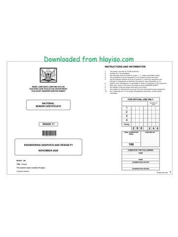
FOR OFFICIAL USE ONLY
1 MODERATED 1
NATIONAL QUESTION MARK OBTAINED 2 SIGN
MARK 2
SENIOR CERTIFICATE 1
2
3
4
GRADE 11 TOTAL
2 0 0 2 0 0
FINAL CONVERTED CHECKED BY
MARK
ENGINEERING GRAPHICS AND DESIGN P1 100
NOVEMBER 2017 COMPLETE THE FOLLOWING:
NAME
NAME
MARKS: 200 EXAMINATION CENTRE
TIME: 3 hours
EXAMINATION CENTRE
This question paper consists of 6 pages. *IGRDSE1*
Copyright reserved Please turn over 1
Skip to contentAll 2017 papers 
View all
Engineering Graphics and Design Grade 11 P1 2017 QP (Eng)
Grade 11 Engineering Graphics and Design Paper 1 question paper from the Eastern Cape November 2017 (English), 6 pages. Read online or download the free PDF.
Engineering Graphic And Design · Grade 11 · Eastern Cape November · 2017. Question paper, 6 pages. Read online or download the PDF.
- Subject
- Engineering Graphics and Design
- Grade
- Grade 11
- Document type
- Question paper
- Year
- 2017
- Exam period
- Eastern Cape November
- Paper
- 1
- Curriculum
- CAPS
- Pages
- 6
- File size
- 2.1 MB
Free to read online, no sign-up needed
Loading document…
Loading document…
1 of 6
This exam
Eastern Cape November 2017
Document textSearch extracted text and jump to a page.
Engineering graphichs and design / P1 Downloaded from hlayiso.com NOTE:
NCS EC DBE/November 2017
Contractors must verify all dimensions and QUESTION 1A: ANALYTICAL (CIVIL)
ST
AP levels on site before commencing work.
LE
1000 1500 1500 Architects to be notified immediately of any Given:
discrepancies.
Two views of a proposed new house. A title panel and a table of questions. The drawing has not been prepared to
1100 the indicated scale.
2700 ARCHITECT'S SIGNATURE ...........................
CLIENT'S SIGNATURE ................................... Instructions:
Complete the table below by neatly answering the questions, which refer to the accompanying drawing and title
VIEW 1 panel. [27]
QUESTIONS ANSWERS
ANSWER 17
C B
16400 In the space provided below, draw, in 1 What is the reference code for the drawing? 1
100 A neat freehand, the front view and top
2 Who checked the drawing? 1
view of the SANS 10143 convention
BEDROOM GARAGE for a WATER CLOSET. 3 What scale is indicated for the drawing? 1
BATH- CARPET GRANO
ROOM 3500 4 Which drawing is this in the set of drawings? 1
4800
BEDROOM TILE 1:10
CARPET 5 What floor finish will be used for the bathroom? 1
1200
4210 6 What does the entire symbol at A mean? 1
2 X 40 W
1310 1700
7 What feature is indicated by B? 1
D E
8 What feature is indicated by C? 1
4100 OPEN PLAN AREA
3700 9 What featurel is indicated by D? 1
TILE
F 10 What electrical symbol is indicated by E? 1
200 200 11 What electrical symbol is indicated by F? 1
6200 7300
12 Which elevation is VIEW 1 ? 1
VIEW 2
13 What should VIEW 2 be labelled? 1
In the adjacent block, in neat freehand, draw the hatching
14 1
for brickwork.
15 In the space provided below, determine the perimeter of the entire house in meters. 3
QUESTION 1B: ELECTRONICS In the space provided below, determine the total area of the wall in VIEW 1 (high lighted) in square
16 4
A 2017-11-12 HATCH WALLS meters.
Given:
A diagram with labels of electronic components. In the space provided in the title panel, draw, in neat freehand, the front view and top view of the
REVISION DATE DESCRIPTION 17 6
A panel with symbols of electronic components. SABS 10143 convention for a WATER CLOSET.
Instructions: DREW ARCHITECTS TOTAL 27
Draw the diagram using the electronic symbols in free hand in the adjacent ELECTRONIC COMPONENT SYMBOLS
space provided. [10] PO BOX 65 TEL: 0461234567
nV
SWITCH FAX: 0961325234
6 V BATTERY NORMALLY
Mc Lear EMAIL: drewarc@mweb.co.za M
CLOSED
6511
+
PRINTED BY DATE OF PRINT
VARIABLE
LAMP RESISTOR KWIK PRINT 2017-11-20
DRAWING TITLE ANSWER 15 ANSWER 16
HOUSE PLAN AND ELEVATION Show ALL calculations. Show ALL calculations.
PROJECT
RESISTOR
PROPOSED NEW HOUSE FOR
MR. N. NONGKAWUSE ON
STAND 862, LUSIKISIKI,
EASTERN CAPE.
PROJECT NUMBER DRAWING NUMBER
456PET 4 OF 4
MARKS
NPN DATE DRAWN CHECKED SCALE Q 1A 27
TRANSISTOR NAME
BUZZER 2017-11-10 DIRK DLABA 1 : 300
Q 1B 10
REFERENCE CODE
FYI1-2017 TOT 37 NAME 2
Copyright reserved Please turn over
Engineering graphichs and design / P1 Downloaded from hlayiso.com
NCS EC DBE/November 2017
QUESTION 2: INTERPENETRATION AND
ST
AP DEVELOPMENT
LE X1
Given:
F The front view and the incomplete left view of a transition
piece that must be made from a single sheet of steel. The
top edge of the transition piece must be welded on each of
the four sides. EF is the seam.
On the answer sheet, the XY planes for the orthographic
drawing and the origin EF for the development.
Instructions:
Draw, to scale 1 : 1, the following views of the transition
piece:
2.1 The complete front view,
2.2 The complete left view,
2.3 The complete top view,
2.4 Develop the surface of the transition piece.
Show ALL constructions, hidden detail and fold lines.
[38]
X Y E
70 70
20
F
F'
70
20
E E'
20
Y1
ASSESSMENT CRITERIA
1 FRONT VIEW 3
2 LEFT VIEW 4
3 TOP VIEW 4 21
4 TRUE LENGHTS 6
DEVELOPMENT +
5 CONSTRUCTION
20 21
PENALTIES (-)
TOTAL 38
NAME
NAME 3
Copyright reserved Please turn over
Engineering graphichs and design / P1 Downloaded from hlayiso.com NCS
QUESTION 3: PERSPECTIVE
EC DBE/November 2017
ST
AP
LE
Given:
Two views of an entrance to a library and the
information needed to draw a two-point
perspective drawing
PP − Picture plane
RO HL − Horizon line
OM GL − Ground line
SP − Station point
DO
OR Instructions:
OP Complete the perspective drawing.
AT EN SE
ING AT
SE · Align the drawing sheet with the ground line
(GL).
· Determine and label the vanishing points.
· Show ALL necessary construction.
· Show the wall thickness at the openings.
· NO hidden detail is required. [40]
ST
EP PILLAR
S
ASSESSMENT CRITERIA
1 CONSTRUCTION + VPs 8
2 STEPS 9
3 WALLS 13
4 OPENINGS 4
PP
5 ROOF 6
TOTAL 40
HL HL
DOOR OPENING
SEAT SEAT SEAT SEAT
STEPS STEPS
GL
SP EXAMINATION NUMBER
EXAMINATION NUMBER 4
Copyright reserved Please turn over
Engineering graphichs and design / P1 Downloaded from hlayiso.com NCS
QUESTION 4: CIVIL DRAWING
EC DBE/November 2017
ST
AP SLIDING DOOR OPENING
LE
1184 Given:
WINDOW OPENING
· The incomplete north elevation of a proposed new flat,
1 showing the walls, window, steps and the door opening
· The incomplete floor plan showing the walls, position of the
2700 doors, windows, built in cupboards and sanitary fixtures
STEP
300 · The incomplete foundation and wall detail
150 ROOM DESIGNATIONS AND
· Room designations and floor finishes
2 FLOOR FINISHES
GROUND LINE · A door and window schedule
INCOMPLETE NORTH ELEVATION 3 1 BEDROOM: CARPET · A table of sanitary fixtures
2 BATHROOM: TILE · The floor plan of the new flat, drawn to scale 1 : 50 and the
3 PASSAGE: TILE starting point for the sectional view drawn to scale 1 : 20 on
4 OPEN PLAN: TILE
page 6
W3 W3 FEATURES
4 Instructions:
D1 DOOR
D2 SLIDING DOOR Answer this question on page 6.
1700
W1 WINDOW
D1 W2 WINDOW 4.1 Using the given incomplete floor plan,on page 6 draw , in
SH WC BIC W3 WINDOW first-angle orthographic projection and to scale 1 : 50, the
BIC following views of the new flat:
FIXTURES
W2 D1 WC TOILET
W1
WB WB WASH BASIN 4.1.1 THE COMPLETE FLOOR PLAN
SH SHOWER Add the following features to the drawing:
S
S SINK
BIC BUILT IN CUPBOARD
DOOR AND WINDOW SCHEDULE · ALL doors, windows and steps
D1 · ALL fixtures as indicated by the abbreviations on page 5
W1 1000 TO FIT 50 1700 · ALL hatching detail
400
4.1.2 THE NORTH ELEVATION
D2
Show the following features on the drawing:
1200
INCOMPLETE FLOOR PLAN · The outside walls, window, steps and door detail
· The finished floor level
2100 2100
WINDOW (W1)
4.2 In the space provided on page 6, draw, to scale 1 : 20,
600
a DETAILED SECTION according to cutting plane A-A of
200 100
the area in the ellipse shown on the floor plan
800 · Show the following features on this view:
150 x 220 mm 150 x 100 mm
LINTEL ABOVE LINTEL ABOVE · The complete foundation, external wall, and window
WINDOW DOOR OPENING WINDOW (W2) SLIDING DOOR detail
1500 DOOR FRAME AND
OPENING FRAME AND DOOR · ALL hatching detail. ONLY the substructure hatching
DOOR (D1)
400 (D2)
may be drawn in neat freehand.
· The lintels above the door and windows
NOTE: 175 x 20 mm · The complete foundation, internal wall and door detail
1200
2700 FIBRE CEMENT · All visible sanitary fixtures
SILL UNDER ALL
WINDOWS Label the following:
WINDOW (W3) · The north elevation including the scale
· The room designations and floor finishes
25 mm SCREED 25 mm SCREED SANITARY FIXTURES · Using the correct abbreviations, label the following features in
the correct view: natural ground level, finished floor level and
500
110 400 damp proof course
GROUND LEVEL
700 400
455 NOTE:
200 200 850 200 850 850
750 ALL drawings must comply with the guidelines and graphical
600 400 100
400 symbols contained in the SANS 10143. [85]
FLOOR LEVEL
INCOMPLETE
INCOMPLETE
FOUNDATION AND
FOUNDATION AND 500 350
EXTERNAL WALL 400 600 200
DETAIL
INTERNAL WALL DETAIL 850
1200
WASH BASIN TOILET SINK (S)
SHOWER
(WB) (WC)
(SH)
5
Copyright reserved Please turn over
Engineering graphichs and design / P1 Downloaded from hlayiso.com
NCS
OFFICIAL USE
EC DBE/November 2017
ST
AP
LE 1 INCORRECT OVERALL SCALE
2 INCORRECT POSITIONING OF VIEWS
3 NON-ALIGNMENT OF VIEWS
TOTAL PENALTIES (-)
ASSESSMENT CRITERIA
FLOOR PLAN
DOORS +
1 WINDOWS + STEPS 19
2 FIXTURES 11 21
3 HATCHING 6
4 LABELS 4
SUBTOTAL 40 21
NORTH ELEVATION
1 WALLS + STEPS 5 21
2 SLIDING DOOR 3
3 WINDOW 4
A A 4 LABELS 2
SUBTOTAL 14 21
DETAILED SECTION
FOUNDATIONS +
1 WALLS + SLAB + 12
LINTELS
2 DOOR + WINDOW 4
3 HATCHING 8
4 LABELS 2
STARTING POINT FOR 5 FIXTURES 4
DETAILED SECTION
SUBTOTAL 30
(EXTERNAL WALL
FOUNDATION) TOTAL 85
PENALTIES (-)
FINAL TOTAL
SECTION A-A
FLOOR PLAN NAME
SCALE 1 : 20
SCALE 1 : 50
NAME 6
Copyright reserved
Study this subject
Recommended for this subject
Question paper
Engineering Graphics and Design Grade 11 P1 2017 QP (Afr)
Memorandum
Engineering Graphics and Design Grade 11 P1 2017 Memo
Question paper
Engineering Graphics and Design Grade 11 P2 2017 QP (Eng)
Question paper
Engineering Graphics and Design Grade 11 P2 2017 QP (Afr)
Question paper
Engineering Graphics and Design Grade 11 P1 2020 QP (Eng)
Question paper
Engineering Graphics and Design Grade 11 P1 2020 QP (Afr)
More from Grade 11 Engineering Graphics and Design
Annual teaching plan
Gr 11 EngGraph Des ATP 2023 24
Memorandum
Engineering Graphics and Design Grade 11 P1 2022 Memo (Afr)
Memorandum
Engineering Graphics and Design Grade 11 P2 2022 Memo (Afr)
Memorandum
Engineering Graphics and Design Grade 11 P2 2022 Memo (Eng)
Memorandum
Engineering Graphics and Design Grade 11 P1 2022 Memo (Eng)
Memorandum