
. e
ok
Cg
ss
basic education
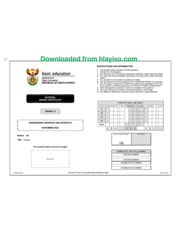
INSTRUCTIONS AND INFORMATION
This question paper consists of FOUR questions.
Answer ALL the questions.
ALL drawings are in first-angle orthographic projection, unless otherwise stated.
Department:
Basic Education
NATIONAL
SENIOR CERTIFICATE
MARKS: 100
TIME: 3 hours
This question paper consists of 6 pages.
|
|
|
| Barcode label
|
|
|
Copyright reserved
REPUBLIC OF SOUTH AFRICA
PONS
ALL drawings must be prepared using pencil and instruments, unless otherwise
stated.
ALL answers must be drawn accurately and neatly.
ALL the questions must be answered on the QUESTION PAPER, as instructed.
ALL the pages, irrespective of whether the question was attempted or not, must
be re-stapled in numerical sequence in the TOP LEFT-HAND CORNER ONLY.
8. Time management is essential in order to complete all the questions.
9. Print your examination number in the block provided on every page.
10.
Non
Any details or dimensions not given must be assumed in good proportion.
FOR OFFICIAL USE ONLY
QUESTION | MARKS OBTAINED |} SIGN | MODERATED | 3] SIGN | REMARKING | 4] SIGN
1
2
Ss
4
TOTAL
2|0|0 2|0/0 2|0/0
FINAL CONVERTED MARK CHECKED BY
100
COMPLETE THE FOLLOWING:
CENTRE NUMBER
| CENTRE NUMBER
EXAMINATION NUMBER
EXAMINATION NUMBER
DO NOT FOLD THIS QUESTION PAPER IN HALF.
Please tum over
Skip to contentAll 2023 papers 
View all





Engineering Graphics and Design Grade 12 P1 2023 QP (Eng)
Grade 12 Engineering Graphics and Design Paper 1 question paper from the NSC November Exam 2023 (English), 6 pages. Read online or download the free PDF.
Engineering Graphic And Design · Grade 12 · NSC November Exam · 2023. Question paper, 6 pages. Read online or download the PDF.
- Subject
- Engineering Graphics and Design
- Grade
- Grade 12
- Document type
- Question paper
- Year
- 2023
- Exam period
- NSC November Exam
- Paper
- 1
- Curriculum
- CAPS
- Pages
- 6
- File size
- 2.3 MB
Free to read online, no sign-up needed
Loading document…
Loading document…
1 of 6
This exam
NSC November Exam 2023
Questions in this paper
Document textSearch extracted text and jump to a page.
Engineering Graphics and Design/P1
Downloaded from hlayiso.com
DBE/November 2023
> SYMBOL LEGEND: NOTE QUESTION 1: ANALYTICAL (CIVIL)
gs LAND SURVEYOR'S CERTIFICATE OF THE: Contractors must verify all dimensions and
‘s CORNER HEIGHTS AND BOUNDARY 1. PALM TREE levels on site before commencing work. a
LENGTHS OF LOT 22 Architects to be notified immediately of any | Given:
2 EVERGREEN discrepancies The site plan of an existing service station with a proposed new fast-food outlet and a covered walkway, a title panel
CORNER HEIGHTS BOUNDARY TREE and a table of questions. The drawing is not presented to the indicated scale.
INMETRES | LENGTHS Iv ancuneers stTune
3. PARKING FOR ° CLIENTS SIGNATURE Instructions:
A 350 AB | 40000 PEOPLE WITH fos Complete the table below by neatly answering the questions, which refer to the accompanying drawing, title panel and
B 351 Bo 78000 DISABILITIES ~ ANSWER 21 civil content. [30]
In the space below, draw, in neat
c 349 cp | 23340 freehand, the SANS 10143
graphical symbol for: QUESTIONS ANSWERS
o 349 OE 7500 (a) SHOWER (elevation and plan)
E 349 EA 44560 (b) SOCKET OUTLET 1 | Whatis the e-mail address of the architectural firm? 1
(a) SHOWER (elevation and plan) | | 2 | What scale is indicated for the site plan? 1
3 | When was the first revision made to the drawing? 1
a 4_ | Into which street does the service station exit? 1
5 | Whatis the height of the highest corner of LOT 22 in metres? 1
LOT 24 6 | Whatis the finish on all the existing driveways? 1
4,8 m HIGH BOUNDARY FENCE Ay 7 |How many existing underground fuel tanks are shown? 4
(bl) SOCKET OUTLET
ve 8 | On what feature in the road is the zebra crossing? 4
) 3000 BL |
2 9. | Whatis the fall of the existing sewer line? 1
zou § EXISTING UNDERGROUND ¥ 40 | What is the height of the electronic display board in millimetres? 1
z a FA r FUEL TANKS es
gouty oem EXISTING © «s ~ SRST 11 | What does the abbreviation @ at 1 stand for? 1
a 2 é Ay REO PETROL PUMP 3 G 2 | 04/02/2023 | concrete APRON | 12 | Name the feature at 2 1
62 7 a
BOs + (ipsphoor a + | so1012023 | NEWENTRANCE | 13 | What does the feature at 3 indicate? 1
|! | & ADDED
z 2 14 | To what must the new sewerage line be connected? 1
sg REVISION DATE DESCRIPTION
bor 20) | Zl L 45 | What is the thickness of the concrete apron in metres? 1
EXISTING
al PETROL PUMP 2 AE ARCHITECTS. 46 | In what colour must new walkways be indicated on site plans? 1
wg EXISTING 17 ALPINE ROAD 7 >
g22 | | BULOING | & [ALPINE ROAI sceancannacon | 17_| Which elevation of the new fast-food outlet faces 7th Avenue’ 2
BES het | EXBSTING 4091 31208 2486, 4g. | fwall S-S on the new fast-food outlet is 4,8 m from boundary line A
x20 ' Ggz PETROL PUMP 1 AB, how far is it from building line T-T in millimetres?
age | Bes PRINTED BY: DATE OF PRINT
wes ty: aug 150 CONGRETE PRINTFRIEND 19 |In the space below (ANSWER 19), determine the perimeter of LOT 22 in metres. 3
| 2g of APRON PRINTERS 05/02/2023
2.3 + ros SaAWNO TE 20 |In the space below (ANSWER 20), determine the total area of the existing building in square metres. | 3
we
588 | SITE PLAN 2 | If the space in the fitle panel (ANSWER 21), draw, in neat freehand, the SANS 10143 graphical A
582 / [ ¢7}_ prick Pavitic LAID on symbol for: (a) SHOWER (elevation and plan) and (b) SOCKET OUTLET
are} t 4 ALL EXISTINGIDRIVEWAYS, PRONECT:
8 i PROPOSED NEW FAST-FOOD OUTLET TOTAL | 30
L "AND COVERED WALKWAY FOR
- LAHRIE AND ASSOCIATES, ANSWER 19 ANSWER 20
LOT 22, 7th AVENUE, KLOOF Show ALL calculations. 6200 Show ALL calculations.
clive (Do NOT round off the answer.) 4 4 (Do NOT round off the answer.)
6meEXIT PROJECT NUMBER: DRAWING NUMBER:
D 72846-23 LA - 787976 pt 800
= ELECTRONIC DATE: DRAWN: CHECKED: | SCALE: iy
= DISPLAY BOARD 2eiot2023/s motaLa | Bux | 1: 450
QUALITY STREET 6m WIDE | == 7500 (W) x 100 (0) x 2500 (H) aR Ee 3
ZESHA GROSSING ON terested 2 g
a,omWIDE SPEED HUMP exstins | 218
g
& SITE PLAN EXAMINATION NUMBER
‘SCALE 1: 450
-—10000__} EXAMINATION NUMBER [2
Copyright reserved
Please tum over
sna Downloaded from hlayiso.com —
oe QUESTION 2: SOLID GEOMETRY
‘3s
Given:
© The front view and top view of a right regular
pentagonal pyramid with one base edge in
contact with a base edge of a right regular
hexagonal prism. The prism is centrally
pierced by a right square prismatic hole.
Cutting plane P-P, that cuts both solids
Instructions:
Draw, to scale 1 : 1, the following views of both
solids:
2.1 The given front view
2.2 A sectional top view
2.3 A sectional left view
Planning is essential
Show ALL hidden detail
Show ALL construction. [38]
x Y
ASSESSMENT CRITERIA
1 |sectionaL Top view | 154]
2 |rront view a}
3 |SecTIONAL LEFT VIEW | 14
PENALTIES ()
TOTAL| 38
EXAMINATION NUMBER
EXAMINATION NUMBER [3
Copyright reserved Please tum over
Engineering Graphics and Design/P1
Downloaded from hlayiso.com —
QUESTION 3: PERSPECTIVE
Given:
Three views of a covered drive-through ticket booth and the
information needed to draw a two-point perspective drawing
PP - Picture plane
HL - Horizon line
GL ~ Ground line
SP ~ Station point
Instructions:
Complete the perspective drawing
* Align the drawing sheet with the ground line (GL).
* Determine and label the vanishing points.
* Show ALL construction.
* Show depth at the window.
* Show ALL interior detail as seen through the window.
* NO hidden detail is required. [40]
ASSESSMENT CRITERIA
4 | CONSTRUCTION 6
2 | FLOOR 11
3 | wats 83
4 | ROOF 43
5 | wINDows + ARC 10
PENALTIES ()
TOTAL | 40
PP
IB
~~
HL. 7 _| HE
i
\
\
'
\
po
Lo r 1
1 ' '
' i \
' | | |e
i i \
' | |
\ ' '
ro ' '
\ \ \
| | |
' ' '
| | H 4
GL
EXAMINATION NUMBER
EXAMINATION NUMBER: [4
Copyright reserved
Please tum over
Engineering Graphics and Design/P1
Downloaded from hlayiso.com
DBE/November 2023
300 x 75 mm BARGE BOARD
10 mm CEILING BOARD ON 40 x 40 mm
BRANDERING STRIPS @ 450 mm clc
INCOMPLETE FOUNDATION
AND EXTERNAL WALL DETAIL
ee RO cm
RIDGE CAP
10 x 100 mm GUTTER ON 200 x 20 mm FASCIA BOARD
FLOOR FINISHES
s 80 mm RWDP THAT STOPS 50 mm 1. OPEN AREA: TILE
‘ABOVE GROUND LEVEL 2, BATHROOM — TILE
8 WINDOW OPENING 3. BEDROOM: CARPET
g . SLIDING DOOR OPENING 4, OFFICE: LAMINATE
[ |— 150 x 300 mm FRONT STEPS WITH SIDE WALLS,
}--—-—-+--—- — FINISHED FLOOR LEVEL
\ GROUND LEVEL
INCOMPLETE NORTH-EAST ELEVATION ROOM DESIGNATIONS
Pw wo — FEATURES DOOR AND WINDOW SCHEDULE
H D1 SLIDING DOOR
i D2 DOOR ye TO FIT 4 Tort t 50 a
H wW1 WINDOW 600 "f “500,
J w2 WINDOW oa S
5
i Wc TOILET al ol
i WB WASH BASIN 3 8
5 8 x
' ELECTRICAL FITTINGS
L 1. ONE-WAY SWITCH - SINGLE-POLE | || B WINDOW (W1)
2. TWO-WAY SWITCH
3. FLUORESCENT LIGHT 4 x 40 W 800
4, CEILING LIGHT aS ur A
5. SWITCHED SOCKET OUTLET F DOOR (02) x
&) INCOMPLETE FLOOR PLAN 6, DISTRIBUTION BOARD SLIDING DOOR (01) 2 e A
600 NOTE : ®
“00, % THE ARROW SHOWS THE LIGHT eee NANG IDE
x CONNECTION TO THE SWITCH. - x
ss + B= FIXED PANEL wanDOW 2)
A g 8 * ALL FRAMES = 50 mm THICK
g 2 8 + 200 x 20 mm FIBRE CEMENT SILL UNDER ALL WINDOWS
X + = GROUND LEVEL
tr Fe =“ ROOF COMPONENTS ELECTRICAL SYMBOLS.
FRONT STEP AND SIDE WALL DETAIL =
. — 200 x 20 mm FASCIA BOARD A
1
200 gad
109 150 x 100 mm GUTTER
/ LE
e in 75 x 50 mm PURLINS Ss
‘| F~1009
oa \ &
- 300 x 75 mm BARGE BOARD
L- | + CT
od 200 xX bowl
‘ps0eG, al 4200_ | ROOF GAP AND RIDGE CAP KX Iieow
INCOMPLETE SCHEMATIC DIAGRAM OF | F]—200 x 80 mm —
ROOF TRUSS AT CUTTING PLANE A-A LINTELS ABOVE
ROOF NOTES: \ [2} ALL DOOR FIXTURES
20° ROOF PITCH ‘AND WINDOW 1500
OPENINGS # 4 450 y 500
114 x 40 mm ROOF TRUSSES ON 2 4700 * st
3 4100 __y g
114 x 40 mm WALL PLATES sg x A 3 as A a
400 mm ROOF OVERHANG TO END OF a 3 J 500 3 be
ROOF TRUSS aor
40 mm CORRUGATED ROOF SHEET ON * sy
75 x 50 mm PURLINS @ 1000 mm cle ss—a g 2©
ale
300 x 75 mm BARGE BOARD ON GABLE ENDS AND aN son XM
200 x 20 mm FASCIA BOARD WITH
450 x 100 mm GUTTERS ON ALL SIDES BATH SINK TOILET WASH BASIN
(8) (s) (we) (WB)
QUESTION 4: CIVIL DRAWING
Given:
* The incomplete north-east elevation of a new house,
showing the walls, the window and sliding door openings, the
front steps, roof and labels
* The incomplete floor plan showing the walls, front steps,
positions of the doors, windows, fixtures and electrical layout
* The front step and side wall detail
* An incomplete schematic diagram of a roof truss at cutting
plane A-A and roof notes
* The incomplete foundation and external wall detail
* Room designations and floor finishes
* A door and window schedule
* A table of roof components
* A table of electrical symbols
* A table of fixtures
* The incomplete floor plan and ground level of the new
house, drawn to scale 1 : 50, and the incomplete foundation
and break lines for the detalled section, drawn to scale 1 : 20,
on page 6
Instructions:
Answer this question on page 6
4.1. Using the given incomplete floor plan and ground level,
draw, to scale 1 : 50, the following views of the new
house:
4.1.1 THE COMPLETE FLOOR PLAN
‘Add the following features to the drawing:
* ALL doors and windows
* ALL fixtures as indicated by abbreviations
* ALL electrical fittings as indicated by the numbers
* ALL hatching detail
4.1.2 THE COMPLETE NORTH-EAST ELEVATION
Show the following features on the drawing:
* The outside walls, window, sliding door and step detail
* The roof detail including the fascia boards, barge board,
gutters and rainwater down-pipe
* The finished floor level
Using the incomplete foundation and break lines on
page 6, draw, to scale 1 : 20, a DETAILED SECTION on
cutting plane A-A of the area in the ellipse shown on the
incomplete floor plan.
Show the following features on the drawing:
* The complete foundation, external wall, slab and
window detail
* The roof detail including ALL rainwater items
* The W2 window, roof and rainwater item detail, to the
right (north-west) of cutting plane A-A
* ALL hatching detail. ONLY the substructure hatching
may be drawn in neat freehand.
4.2
Label the following:
© The floor finishes
* Ground level, finished floor level and damp-proof course
(use the correct abbreviations and show them on ALL
relevant views)
NOTE:
ALL drawings must comply with the guidelines and
graphical symbols as contained in the SANS 10143.
[92]
[5
Copyright reserved
Please tum over
Engineering Graphics and Design/P1
Downloaded from hlayiso.com
DBE/November 2023
GL
NORTH-EAST ELEVATION
woe yl
|
| |
| |
| |
| BEDROOM BATHROOM |
| |
| |
| |
wy |
S| |
i
dl I
9
al |
| |
| I
| OFFICE |
| |
| >b 7 / |
| Z 4 |
|
I o RWDP 71 ia |
ee — /
ne y |
| / |
| |
| |
| |
> | |
oe pp Ny
FLOOR PLAN
SCALE 1 : 50
SECTION A-A
SCALE 1 : 20
rane FOR OFFICIAL USE ONLY
SECTION OF ROOF | | ncorRECT
A SCALE(S) USED
B NON-ALIGNMENT OF
¢ VIEW(S) ROTATED
° SECTION VIEWED
E INCORRECTLY
F LETTERING.
G
H
J
TOTAL TOTAL
ASSESSMENT CRITERIA
FLOOR PLAN
posite | ostaneo | sion | monerareD
1 | fivoows | 132
2 | rwrures 8
3 |etecrrica | ot
4 | warcune 3
S | tasers 2
SUBTOTAL 36
NORTH-EAST ELEVATION
1 | woe” 83
2 | Sres” 7
3 | winoow 8
4 [vse 3
SUBTOTAL 24
DETAILED SECTION
41 |Roor vera | 433
2 |susewar] 44
3 | arcrine 54
4 | wwoons 7
5 | uses 14
SUBTOTAL 32
TOTAL 92
PENALTIES ()
GRAND TOTAL
EXAMINATION NUMBER
EXAMINATION NUMBER: [6
Copyright reserved
Study this subject
Recommended for this subject
Question paper
Engineering Graphics and Design Grade 12 P2 2023 QP (Afr)
Question paper
Engineering Graphics and Design Grade 12 P2 2023 QP (Eng)
Question paper
Engineering Graphics and Design Grade 12 P1 2022 QP (Eng)
Question paper
Engineering Graphics and Design Grade 12 P1 2021 QP (Afr)
Question paper
Engineering Graphics and Design Grade 12 P1 2020 QP (Eng)
Question paper
Engineering Graphics and Design Grade 12 P1 2019 QP (Afr)
More from Grade 12 Engineering Graphics and Design
Memorandum
Engineering Graphics and Design Grade 12 P1 2025 Memo
Memorandum
Engineering Graphics and Design Grade 12 P2 2025 Memo (Eng)
Memorandum
Engineering Graphics and Design Grade 12 P2 2025 Memo
Memorandum
Engineering Graphics and Design Grade 12 P2 2024 Memo (Eng)
Memorandum
Engineering Graphics and Design Grade 12 P1 2023 Memo (Afr)
Question paper