
. e
ok
Cg
ss
basic education
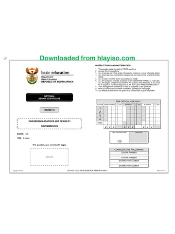
INSTRUCTIONS AND INFORMATION
This question paper consists of FOUR questions.
Answer ALL the questions.
ALL drawings are in third-angle orthographic projection, unless otherwise stated.
Department:
Basic Education
NATIONAL
SENIOR CERTIFICATE
MARKS: 100
TIME: 3 hours
This question paper consists of 6 pages.
|
|
|
| Barcode label
|
|
|
Copyright reserved
REPUBLIC OF SOUTH AFRICA
PONS
ALL drawings must be prepared using pencil and instruments, unless otherwise
stated.
ALL answers must be drawn accurately and neatly.
ALL the questions must be answered on the QUESTION PAPER, as instructed.
ALL the pages, irrespective of whether the question was attempted or not, must
be re-stapled in numerical sequence in the TOP LEFT-HAND CORNER ONLY.
8. Time management is essential in order to complete all the questions.
9. Print your examination number in the block provided on every page.
10.
NO
Any details or dimensions not given must be assumed in good proportion.
FOR OFFICIAL USE ONLY
QUESTION | MARKS OBTAINED |} | SIGN | MODERATED | 3] SIGN | REMARKING | 3] SIGN
1
2
Ss
4
TOTAL
2|0|0 2|0/0 2|0/0
FINAL CONVERTED MARK CHECKED BY
100
COMPLETE THE FOLLOWING:
CENTRE NUMBER
| CENTRE NUMBER
EXAMINATION NUMBER
EXAMINATION NUMBER
DO NOT FOLD THIS QUESTION PAPER IN HALF.
Please tum over
Skip to contentAll 2023 papers 

View all




Engineering Graphics and Design Grade 12 P2 2023 QP (Eng)
Grade 12 Engineering Graphics and Design Paper 2 question paper from the NSC November Exam 2023 (English), 6 pages. Read online or download the free PDF.
Engineering Graphic And Design · Grade 12 · NSC November Exam · 2023. Question paper, 6 pages. Read online or download the PDF.
- Subject
- Engineering Graphics and Design
- Grade
- Grade 12
- Document type
- Question paper
- Year
- 2023
- Exam period
- NSC November Exam
- Paper
- 2
- Curriculum
- CAPS
- Pages
- 6
- File size
- 1.9 MB
Free to read online, no sign-up needed
Loading document…
Loading document…
1 of 6
This exam
NSC November Exam 2023
Questions in this paper
Document textSearch extracted text and jump to a page.
Engineering Graphics and Design/P2
DBE/November 2023
Downloaded fr
R18
SAN
235
ASSEMBLY
VIEW 1
100
VIEW 2
HANDLE
30
\RI4
G=D
SECTION S-S
M5 BOLT (NTS)
RETAINING SPRING
o10
om hlayiso.com
QUESTION 1: ANALYTICAL (MECHANICAL)
Given:
A view of the assembled pipe wrench, third-angle orthographic views of the parts of the pipe wrench, a title block and a
table of questions. The drawings are not presented to the indicated scale.
Instructions:
Complete the table below by neatly answering the questions, which refer to the accompanying drawings, the title block
and mechanical content.
[30]
QUESTIONS
ANSWERS
In which street is the manufacturer situated?
What was done by Charles on 16/08/2022?
oe
What is the file name?
x
What conventional representation is indicated by the break lines
at A?
What heating process is used for the tempering?
What type of section is SECTION S-S?
What type of section is shown in DETAIL T?
e|rlola
Determine the complete dimensions at: B: Cc:
Measure the angle at F.
What is the depth of the teeth at G?
m
a} ajala]a]s
What does the double-dash chain line at H indicate?
How many surfaces on the pipe wrench must be machined?
What does the abbreviation NTS stand for?
If VIEW 1 is the front view of the handle, what would VIEW 2 be
called?
How many parts make up the pipe wrench assembly?
With reference to the tolerance, determine the minimum and the
maximum dimension at J
17
What is the direction of lay that is indicated by the machining
symbol?
18
What does the 0.2 on the machining symbol indicate?
19
In the space below (ANSWER 19), redraw, in neat freehand and to the same size, the given end of a
stud as a SANS 10111 conventional representation.
20
In the space below (ANSWER 20), draw, in neat freehand, the symbol for the projection system used. | 34
sen
RETAINING PIN
TOTAL | 30
FILE NAME: SCGG213
DRAWING No. WRC13
TOLERANCE:
40,23
-0,10
JJ HAND TOOLS CC
www toolsce.co.za
84 SHARK STREET
DRAWING PROGRAM: AUTOCAD 2022
SCALE 1
3
DURBAN
0110
CELL: 090 314 5839
HEAT TREATMENT:
TEMPERING - 860° WITH
INDUCTION HEATING
DRAWN BY: NOMVUNDO-
DATE: 02/07/2022
ALL UNSPECIFIED RADII ARE R4,
02
CHECKED BY, CHRIS
DATE: 09/08/2022
TITLE: PIPE WRENCH
APPROVED BY: CHARLES,
DATE: 16/08/2022
ASSEMBLY
ANSWER 19.
CN
DETAILED
REPRESENTATION
CONVENTIONAL
REPRESENTATION
ANSWER 20
‘SYMBOL
EXAMINATION NUMBER
EXAMINATION NUMBER: [2
Copyright reserved
Please tum over
Engineering Graphics and Design/P2
DBE/November 2023
Downloaded from hlayiso.com
62
ASSESSMENT CRITERIA 2.1
1
GIVEN 6
2
CONSTRUCTION 3
3
POINTS + CURVE 10
PENALTIES (-)
SUBTOTAL 2.1 19
QUESTION 2: LOCI
NOTE: Answer QUESTIONS 2.1 and 2.2.
2.1 MECHANISM
Given:
* Asschematic drawing of a mechanism
consisting of crank OA, sliding rod AB,
horizontal groove FG and rod DE in the
vertical posision
* The position of centre point O on the
drawing sheet
Specifications and motio
* The positions of centre point O and point D
are fixed.
* Sliding rod AB is pin-jointed at A.
* Guide B slides in groove FG.
* Rod DE is pin-jointed at D.
* Rod DE slides through guide B.
* As crank OA rotates, guide B slides back
and forth in groove FG, causing rod DE to
oscillate.
Instructions:
* Draw, to scale 1; 1, the given schematic
drawing of the mechanism.
* Trace the loci generated by point C and by
point E for ONE complete rotation of
crank OA.
* Show ALL construction. [19]
MAXIMUM
90°
DISPLACEMENT
MINIMUM
DISPLACEMENT 95
180°
30°
60°
90°
120°
150°
180°
ASSESSMENT CRITERIA 2.2
GRAPH CONSTRUCTION
PLOTTING GRAPH
1
2
3
CAM CONSTRUCTION iB
4
CAM + CURVE QUALITY 53
PENALTIES (-)
SUBTOTAL 2.2 19
2.2: CAM
Given:
The wedge-shaped follower and the camshaft,
as well as the first 180° of the cam profile and
the displacement graph in the correct position
Motion:
The cam imparts the following motion to the
given follower over the next 180°:
* There is a dwell period for 45°.
* It moves inwards to the minimum
displacement with uniform acceleration and
retardation over the next 90°
* There is a dwell period over the remainder
of the rotation.
Instructions:
* Using a rotational scale of 10 mm = 30° and
a displacement scale of 1 : 1, complete the
displacement graph by adding the required
motion,
* Label the displacement graph and include
the rotational scale.
* Project and complete the cam profile
* Indicate the rotation direction with an arrow.
* Show ALL construction and projection. [19]
SUBTOTAL 2.1 19
EXAMINATION NUMBER
TOTAL| 38
EXAMINATION NUMBER: [3
Copyright reserved
Please tum over
sun ssiatoa Downloaded from hlayiso.com —
Os QUESTION 3: ISOMETRIC DRAWING
‘és
Given:
© The front view, top view and right view of a
SLIDING GUIDE casting
© The position of point P on the drawing sheet
Instructions:
Using scale 1 : 1, convert the orthographic views
of the SLIDING GUIDE casting into a sectional
isometric drawing on cutting plane A-A.
* Make P the lowest point of the drawing
Show ALL construction.
* NO hidden detail is required. [40]
55 105 16,
20_, 35
>—-}
ka P 48
TOP HALF OF PR |
A HEXAGON
\
| oI /120° ditt
| > |
Li
PS 1 3*
Pp 2 60"\
PI
TPL] Ca]
96
i ASSESSMENT CRITERIA
P 1 [PLACING + AUX. VIEWS 2
2 |FRONT+MIDDLE SURFACES | 20
[SECTIONED SURFACE +
3 |HatTcHING 12
4 orci + cL 6
PENALTIES ()
TOTAL} 40
EXAMINATION NUMBER
EXAMINATION NUMBER [4
Copyright reserved Please tum over
Engineering Graphics and Design/P2
DBE/November 2023
Downloaded from hlayiso.com
30
25 30 39
15_|_15,
R10] \)
34
COUPLING [3]
M10 BOLT + WASHER [4]
M20
@10
@20
— @36
©
| 7 3 ae SEAL [7]
2 HOLES M10
ON 86 PCD / 220 3
BRACKET [1]
40 7
WASHER [8]
@20
FLANGE [6]
16.
4 aN
th OF
LT Bag
WOODRUFF KEY [5]
M20 NUT [9]
EXPLODED ISOMETRIC DRAWING
QUESTION 4: MECHANICAL ASSEMBLY
Given:
* The exploded Isometric drawing of the parts of a coupling
assembly, showing the position of each part relative to all
the others
* Orthographic views of each part of the coupling assembly
Instructions:
Answer this question on page 6
Draw, to scale 1: 1 and in third-angle orthographic
projection, the following views of the assembled parts of the
coupling assembly:
4.1 Asectional front view on cutting plane A-A as seen
from the direction of the arrow on the exploded
isometric drawing. The cutting plane is shown on the
left view of the flange (part 6).
4.2 The left view
NOTE:
* Planning is essential.
* The drawing must comply with the SANS 10117 guidelines.
* The convention of symmetry may NOT be applied.
* Show THREE faces of the M20 NUT (part 9) on the
sectional front view.
* Show TWO faces of the M10 BOLT (part 4) on the sectional
front view.
* NO hidden detail is required. [92]
PARTS LIST
PART QUANTITY | MATERIAL
1 | BRACKET 1 MILD STEEL
2 |BUSH 1 BRONZE
3 | COUPLING 1 MILD STEEL
4, [MIO HEXAGONAL BOLT + 1 STEEL
5 | WOODRUFF KEY 1 MILD STEEL
6 | FLANGE 1 MILD STEEL
7 | SEAL 1 RUBBER
8 | WASHER 1 STEEL
9 | M20 HEXAGONAL NUT 1 STEEL
25 JUSTICE STREET
GLENVIEW
www.bounty.co.za
031 345 7869
COUPLING ASSEMBLY
Og
BOUNTY
ENGINEERING CC
ALL DIMENSIONS ARE IN MILLIMETRES.
Copyright reserved
Please tum over
sun ssiatoa Downloaded from hlayiso.com —
FOR OFFICIAL USE ONLY
Ce INCORREOT ORTHOGRAPHIC PROJECTION
‘
INCORRECT OVERALL SCALE
INCORRECT HATCHING
PARTS NOT ASSEMBLED
TOTAL PENALTIES (-)
ASSESSMENT CRITERIA
LEFT VIEW
1 | sraceer 5
2 | courtinc 6
3 | ruance 53
4 |miorexsor | 35
SUBTOTAL 20
SECTIONAL FRONT VIEW
1 | eracker 103
2 | susH 5
3 | courtine 183
4 | mtonex. aout 8
5 | wor | og
6 | FLaNce 8
7 | sea 2
8 | iteonur 53
SUBTOTAL | 60
GENERAL
7 |cewneunes | 3
2 | assemay 9
SUBTOTAL | 12
TOTAL| 92
PENALTIES (-)
GRAND TOTAL
EXAMINATION NUMBER
EXAMINATION NUMBER [6
Copyright reserved
Study this subject
Recommended for this subject
Question paper
Engineering Graphics and Design Grade 12 P2 2023 QP (Afr)
Question paper
Engineering Graphics and Design Grade 12 P1 2023 QP (Eng)
Question paper
Engineering Graphics and Design Grade 12 P2 2023 QP
Question paper
Engineering Graphics and Design Grade 12 P2 2023 QP (Afr)
Question paper
Engineering Graphics and Design Grade 12 P2 2022 QP (Afr)
Question paper
Engineering Graphics and Design Grade 12 P2 2019 QP (Afr)
More from Grade 12 Engineering Graphics and Design
Memorandum
Engineering Graphics and Design Grade 12 P1 2025 Memo
Memorandum
Engineering Graphics and Design Grade 12 P2 2025 Memo (Eng)
Memorandum
Engineering Graphics and Design Grade 12 P2 2025 Memo
Memorandum
Engineering Graphics and Design Grade 12 P2 2024 Memo (Eng)
Memorandum
Engineering Graphics and Design Grade 12 P1 2023 Memo (Afr)
Memorandum