
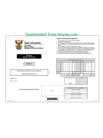
basic education
Department
« y) Basic Education
"4 REPUBLIC OF SOUTH AFRICA
NATIONAL
SENIOR CERTIFICATE
.
i ENGINEERING GRAPHICS AND DESIGN P2 \
i] iit
i FEBRUARY/MARCH 2017 j
Y
MARKS: 100
TIME: 3 hours
This question paper consists of 6 pages.
INSTRUCTIONS AND INFORMATION
This question paper consists of FOUR questions.
Answer ALL the questions.
ALL orthographic drawings are in third-angle projection, unless otherwise stated.
ALL drawings must be completed using instruments, unless otherwise stated.
ALL answers must be drawn accurately and neatly.
ALL the questions must be answered on the QUESTION PAPER as instructed.
ALL the pages, irrespective of whether the question was attempted or not, must
be re-stapled in numerical sequence in the TOP LEFT-HAND CORNER ONLY.
8. Proper planning is essential in order to complete all the questions.
9. Print your examination number in the block provided on every page.
10. Any details or dimensions not given must be assumed in good proportion.
NOARON>
FOR OFFICIAL USE ONLY
QUESTION |] MARKS OBTAINED | 3 | SIGN MODERATED 3] SIGN RE-MARKING 2 | SIGN
1
2
3
4
TOTAL
2/0/0 2/;0/0 2/0/0
FINAL CONVERTED MARK CHECKED BY
100
COMPLETE THE FOLLOWING:
CENTRE NUMBER
CENTRE NUMBER
EXAMINATION NUMBER
EXAMINATION NUMBER
Copyright reserved
Please tum over
Skip to contentAll 2017 papers 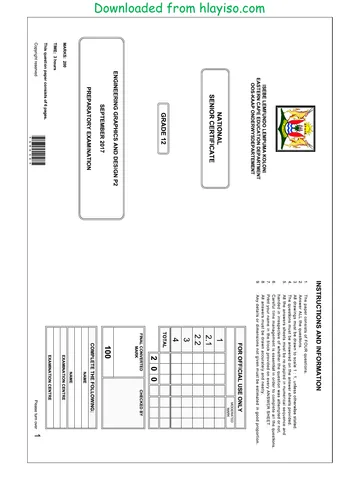
View all
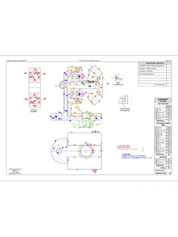
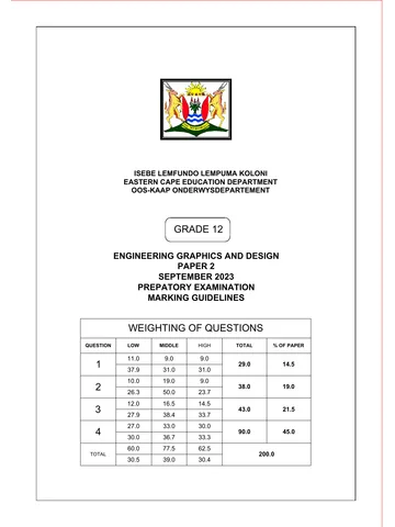
Engineering Graphics and Design Grade 12 P2 2017 QP (Eng)
Grade 12 Engineering Graphics and Design Paper 2 question paper from the NSC Supplementary Exam 2017 (English), 6 pages. Read online or download the free PDF.
Engineering Graphic And Design · Grade 12 · NSC Supplementary Exam · 2017. Question paper, 6 pages. Read online or download the PDF.
- Subject
- Engineering Graphics and Design
- Grade
- Grade 12
- Document type
- Question paper
- Year
- 2017
- Exam period
- NSC Supplementary Exam
- Paper
- 2
- Curriculum
- CAPS
- Pages
- 6
- File size
- 1.5 MB
Free to read online, no sign-up needed
Loading document…
Loading document…
1 of 6
This exam
NSC Supplementary Exam 2017
Questions in this paper
Document textSearch extracted text and jump to a page.
Engineering Graphics and Design/P2
DBE/Feb.-Mar. 2017
40
M22.
Downloaded from hlayiso.com
QUESTION 1; ANALYTICAL (MECHANICAL)
Given:
questions. The drawings have not been prepared to the indicated scale.
M12
Instructions:
block.
An assembly drawing showing two views of a gas regulator assembly, a parts list, a title block and a table of
Complete the table below by neatly answering the questions, which refer to the accompanying drawing and the title
[30]
QUESTIONS
ANSWERS
What is the title of the drawing?
What is the web address of the company?
What method of machining is prescribed?
VIEW 2
Which drawing program was used to prepare the drawing?
On what date was the drawing drawn?
Who approved the drawing?
What material is used to manufacture the seal?
What is VIEW 1 called?
olo}/nljolalaleo|nr
Name the feature at A.
}
Determine the complete dimensions at B: Cc:
11 | Measure the angle at E
12 | Why is the part at F filled in solid?
13 | What is indicated by the feature at G?
14 | Name the type of finish at H
23
a
Refer to the parts list and identify the part at J
How many surfaces of the gas regulator assembly must be
o16
16
machined?
13
17 | Why is the feature at K tapered to one side only?
| 40 18 | Insert the cutting plane on VIEW 2 and label it S-S.
PARTS LIST
VIEW 1 19 | In the space below (ANSWER 19), draw, in neat freehand, the convention for a coil spring. 3
PART
QUANTITY
MATERIAL 90 | In the space below (ANSWER 20), draw, in neat freehand, the symbol for the projection system
1 | PRIMARY BASE
1
used.
BRASS APPROVED: SOON DATE: 2018-12-06
2 | INLET
1
BRASS CHECKED: VERNON DATE: 2015-11-10
TOTAL | 30
ANSWER 19:
e
INLET SEAL
RUBBER DRAWN: WIKUS DATE: 2015-10-31 Convention for a coil spring
4 | INLET SCREW
BRASS DRAWING PROGRAMME: AUTOCAD 2016
VALVE ASSEMBLY
BRASS ALL UNSPECIFIED RADII ARE R2. SCALE 1:1
VALVE SPRING
METHOD OF MACHINING: MILLING
‘SPRING STEEL
DIAPHRAGM ASSEMBLY
DIAPHRAGM
STAINLESS STEEL THE ONE GAS a) soe eee
www.theonegas.coza
RUBBER COMPANY
elelrlola
PRESSURE SPRING
‘= 012 367 8910
SPRING STEEL | TITLE
ANSWER 20:
Projection symbol
10 | CaP
EXAMINATION NUMBER:
BRASS GAS REGULATOR
14 | OUTLET
EXAMINATION NUMBER [2
Copyright reserved
= INNA
Please tum over
Engineering Graphics and Design/P2
xo
ae
é
°
QUESTION 2: LOCI
NOTE: Answer QUESTIONS 2.1 and 2.2.
2.1 LOCI (HELIX)
Given:
* A front view and left view of the shaft of an
auger with Q indicating the starting position pe a - -
* The position of point P on the drawing
sheet
234
if, " AUGER SHAFT DETAIL
Specifications:
Copyright reserved
* Nominal diameter: 274mm
* Pitch : 72mm
© Turns : ONE AND A HALF
* Direction : Left-handed
Instructions: ASSESSMENT CRITERIA 2.1
Draw, to scale 1: 1, the complete front view | 1 | GIVEN+CENTRELINES | 3
and left view of the auger. > | CONSTRUCTION ry
Show ALL construction. 3 | OUTER HELIX 53
* NO hidden detail is required. [23]
4 | INNER HELIX + SHAFT 43
5 | CURVE QUALITY 2
PENALTIES ()
SUBTOTAL 23
2.2 CAM
Given:
The bottom left 0° starting position of the displacement graph on the answer sheet
Motion:
* The follower rises with uniform motion for 15 mm over the first 30° of rotation.
« There is a dwell period for the next 15°.
* The follower rises with simple harmonic motion for 65 mm over the next 135°, to the
maximum displacement of 80 mm.
« There is a dwell period for the next 90°.
« The follower returns with uniform acceleration and retardation to the original position over the
rest of the rotation.
Instructions:
Draw, to a displacement scale of 1: 1 anda
horizontal scale of 360° = 180 mm, the
complete displacement graph for the required ASSESSMENT CRITERIA 2.2
motion.
1 | CONSTRUCTION 6
* Label the graph and indicate the horizontal > | poivts + cuRVES 9
scale.
Show ALL construction [16] | 3 | LAsets 1
PENALTIES ()
2.2 SUBTOTAL 16
2.1 SUBTOTAL 23
TOTAL | 39
EXAMINATION NUMBER
EXAMINATION NUMBER [3
Please tum over,
Engineering Graphics and Design/P2
xo
ae
é
Downloaded from hlayiso.com ee
QUESTION 3: ISOMETRIC DRAWING
Given:
© The front view and top view of a bracket
© The position of point S on the drawing sheet
Instructions:
Using scale 1 : 1, convert the orthographic views of the
bracket to an isometric drawing.
* Make S the lowest point of the drawing.
* Show ALL construction
60
* NO hidden detail is required. [39]
58
45
3|
58
36
T
I 2
| 3|
'
i ces ©
1} (ote ©
|| ial
H
ASSESSMENT CRITERIA
4 | AUXILIARY VIEW + a
PLACEMENT
2 | FRONT + REAR SECTION 25
3 | HEXAGON 4
4 | CIRCLE + CL 8
PENALTIES (-)
TOTAL| 39
EXAMINATION NUMBER
EXAMINATION NUMBER [4
Copyright reserved
Please tum over
semaine Downloaded from hlayiso.com sum
QUESTION 4: MECHANICAL ASSEMBLY
Given:
o * Orthographic views of each of the parts of a tension pulley
"| assembly
an * The exploded isometric drawing of the parts of the tension
pulley assembly, showing the position of each part
relative to all the others
Instructions:
* Answer this question on page 6.
© Draw, to scale 1: 1 and in third-angle orthographic
projection, the following views of the assembled parts of
I Ch) WASHER [8] M12 NUT [9] the tension pulley assembly:
4.1 The front view as seen from the direction of the
arrow shown on the exploded isometric drawing
|
8 7- Le- | + 4.2 Ahalf-sectional top view on cutting plane A-A
i Show the front haif in section, in accordance with
g| Hl the cutting plane that is shown on the left view of
+P t ri PULLEY [7] the housing (part 1).
i] 4.3. The left view
5 _-| 5 —-| |. 5
L | | NOTE:
50 20
* Planning is essential
HOUSING [1] + ALL drawings must comply with the guidelines contained
in the SANS 10111.
* The convention of symmetry may not be applied.
o10 © The spring (part 4) must be drawn in convention and in
neat freehand.
« Show THREE faces of the M12 nut in the top view.
* Add cutting plane A-A.
gq gq * NO hidden detail is required [92]
BUSH [6]
PARTS LIST
PART QUANTITY MATERIAL
1 | HousING 1 MILD STEEL
4 me 2 | FORK 1 CAST IRON
ois f
coy 3 [Pin 1 MILD STEEL
cee
] 4 | SPRING 1 SPRING STEEL
405 Es
2 3 5 | M1280LT 1 MILD STEEL
FORK [2] 2
Al i 6 | BusH 2 BRASS
Vy e 1 8 | WASHER 1 MILD STEEL
| _.| Mit2
9 | wiz. nut 1 MILD STEEL
| T ey _| “TENSION PULLEY
_— “ EXPLODED ISOMETRIC DRAWING 54 PEARL ROAD
GENERAL PERSEVERANCE
6000
Bon M12 BOLT [5] ENGINEERING WORKS #R pei 95 1600
ALL DIMENSIONS ARE | ALL UNSPECIFIED = E
— — ONION — I
Copyright reserved Please tum over
somtntenite Downloaded from hlayiso.com _
FOR OFFICIAL USE ONLY
Cg INCORRECT ORTHOGRAPHIC PROJECTION
é
INCORRECT SCALE
INCORRECT HATCHING
PARTS NOT ASSEMBLED
TOTAL PENALTIES (-)
ASSESSMENT CRITERIA
FRONT VIEW
1 | Housine + PIN EB
2 | FORK 4
3 | PULLEY 1
4 M2 BOLT * WASHER + 6
SUBTOTAL 14
SECTIONAL TOP VIEW
1 | HOUSING + PIN 7
2 | FORK 103
3 | M12 BOLT 7
4 | BUSH 4
5 | PULLEY 7}
6 | WASHER + m2 NUT a4
SUBTOTAL 404
LEFT VIEW
4 | HOUSING 43
2 | FORK 13
3 | SPRING 2
4 | BUSH 1
5 | PULLEY 43
g | MIEBOLT +wasHIER+ | 4
SUBTOTAL 22
GENERAL
1 | CENTRE LINES 63
2 | ASSEMBLY 9
SUBTOTAL 154
TOTAL | 92
PENALTIES (-)
GRAND TOTAL
EXAMINATION NUMBER
INNA sameness 18
Copyright reserved SEAS TOE DUCAT IONS
Study this subject
Recommended for this subject
Question paper
Engineering Graphics and Design Grade 12 P2 2017 QP (Eng)
Question paper
Engineering Graphics and Design Grade 12 P2 2018 QP (Eng)
Question paper
Engineering Graphics and Design Grade 12 P2 2018 QP (Afr)
Question paper
Engineering Graphics and Design Grade 12 P2 2015 QP (Afr)
Memorandum
Engineering Graphics and Design Grade 12 P2 2017 Memo
Memorandum
Engineering Graphics and Design Grade 12 P2 2017 Memo (Eng)
More from Grade 12 Engineering Graphics and Design
Memorandum
Engineering Graphics and Design Grade 12 P1 2025 Memo
Memorandum
Engineering Graphics and Design Grade 12 P2 2025 Memo (Eng)
Memorandum
Engineering Graphics and Design Grade 12 P2 2025 Memo
Memorandum
Engineering Graphics and Design Grade 12 P2 2024 Memo (Eng)
Memorandum
Engineering Graphics and Design Grade 12 P1 2023 Memo (Afr)
Question paper