
basic education
Department
« y) Basic Education
"4 REPUBLIC OF SOUTH AFRICA
NATIONAL
SENIOR CERTIFICATE
.
i ENGINEERING GRAPHICS AND DESIGN P14 \
i] iit
i FEBRUARY/MARCH 2017 j
Y
MARKS: 100
TIME: 3 hours
This question paper consists of 6 pages.
INSTRUCTIONS AND INFORMATION
This question paper consists of FOUR questions.
Answer ALL the questions.
ALL orthographic drawings are in first-angle projection, unless otherwise stated.
ALL drawings must be completed using instruments, unless otherwise stated.
ALL answers must be drawn accurately and neatly.
ALL the questions must be answered on the QUESTION PAPER as instructed.
ALL the pages, irrespective of whether the question was attempted or not, must
be re-stapled in numerical sequence in the TOP LEFT-HAND CORNER ONLY.
Proper planning is essential in order to complete all the questions.
Print your examination number in the block provided on every page.
0. Any details or dimensions not given must be assumed in good proportion.
NOOPON>
goer
FOR OFFICIAL USE ONLY
QUESTION |] MARKS OBTAINED | 3 | SIGN MODERATED 3] SIGN RE-MARKING 2 | SIGN
1
2
3
4
TOTAL
2/0/0 2/;0/0 2/0/0
FINAL CONVERTED MARK CHECKED BY
100
COMPLETE THE FOLLOWING:
CENTRE NUMBER
CENTRE NUMBER
EXAMINATION NUMBER
EXAMINATION NUMBER
Copyright reserved
Please tum over
Skip to contentAll 2017 papers 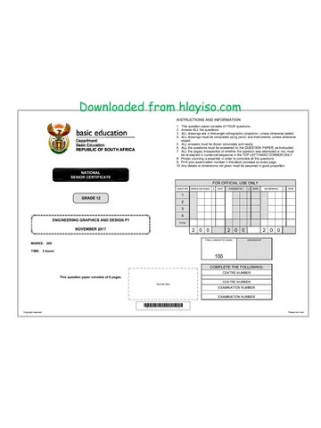
View all
Engineering Graphics and Design Grade 12 P1 2017 QP (Eng)
Grade 12 Engineering Graphics and Design Paper 1 question paper from the NSC Supplementary Exam 2017 (English), 6 pages. Read online or download the free PDF.
Engineering Graphic And Design · Grade 12 · NSC Supplementary Exam · 2017. Question paper, 6 pages. Read online or download the PDF.
- Subject
- Engineering Graphics and Design
- Grade
- Grade 12
- Document type
- Question paper
- Year
- 2017
- Exam period
- NSC Supplementary Exam
- Paper
- 1
- Curriculum
- CAPS
- Pages
- 6
- File size
- 1.9 MB
Free to read online, no sign-up needed
Loading document…
Loading document…
1 of 6
This exam
NSC Supplementary Exam 2017
Questions in this paper
Document textSearch extracted text and jump to a page.
Engineering Graphics and Design/P1
Downloaded fr
DBE/Feb.-Mar. 2017
og
é
30967
8000
LAND SURVEYOR'S CERTIFICATE OF THE.
BOUNDARY LENGTHS AND CORNER
HEIGHTS ON STAND 1932,
SURVEYED ON 2015-09-15
BOUNDARY CORNER HEIGHTS
LENGTHS IN INMETRES
MILLIMETRES
‘AB = 25200 A= 1250
BC = 72000 B= 1251
cD = 50967 c= 1251
DA = 27600 D=1250
AGRICULTURAL LAND.
EXISTING
HOUSE,
STAND
1931
SITE PLAN
SCALE 1: 450
8000 WIDE,
LLOYD WRIGHT LANE
NOTE:
Contractors must verify all dimensions and levels,
on site before commencing work. Architects to
be notified immediately of any discrepancies.
ARCHITECT'S SIGNATURE
CLIENTS SIGNATURE
m_hlayiso.com
QUESTION 1: ANALYTICAL (CIVIL)
Given:
The site plan for a proposed new cottage, a title panel and a table of questions. The drawing has not been prepared to
the indicated scale.
Instructions:
Complete the table below by neatly answering the questions, which refer to the accompanying drawing and title panel.
ANSWER 18 130]
In the space below, draw, in neat
freehand and according to the
SANS 10743, across section of a QUESTIONS ANSWERS
piece of TIMBER or UNDRESSED 1 | On what date was the site plan printed? 1
WOOD.
2 | Who prepared the drawing? 1
3. |How many revisions have been made to the drawing? 1
4 | What is the length of boundary CD? 1
5 | What scale is indicated for the drawing? 1
6 | What does the abbreviation IC stand for? 1
ANSWER 19 _
Inthe space below, draw, in neat 7 | What does the abbreviation RE stand for? 1
freehand, the front view and top view 8 | What does the abbreviation MH stand for? 1
of the SANS 10143 graphic symbol for - —
a WATER CLOSET. g | What is the shortest distance from the existing house to :
STAND 1931 in metres?
10 | What does the ratio at 1 indicate? 1
11 [Name the feature at 2. 1
12 | In what colour should the feature at 3 be shown? 1
43 | Whats the difference in height between comer A and :
corner C in metres?
44 | Why would a residential development not be allowed on 4
PLOT 207?
15 | Which elevation of the existing house faces STAND 1933? 2
16 ||n the space below (ANSWER 16), determine the perimeter of the proposed new cottage in metres. | 3
17 ||n the space below (ANSWER 17), determine the total area of STAND 1932 in square metres. 4
4g |! the space in the title panel (ANSWER 18), draw, in neat freehand and according to the 5
SANS 10143, a cross section of a piece of TIMBER or UNDRESSED WOOD.
4g |" the space in the title panel (ANSWER 19), draw, in neat freehand, the front view and top view of |
Revision | DATE | DESCRIPTION the SANS 10143 graphic symbol for a WATER CLOSET.
TOTAL | 30
PRNTED EY DATE OF PRINT ANSWER 16 ANSWER 17.
FRANK PRINTERS zorsnione Show ALL calculations. Show ALL calculations.
DRAWING THLE
SITE PLAN STAND 1932
PROIECT
PROPOSED NEW COTTAGE
ON STAND 1932, KLIPPLAAT
PROC NUMBER DRAWING NOMBER
GR447-101 447°6
DATE Drawn [oneoED | SOME
2015/10/10 |J VAN WYK] CK BIRD | 1: 450 EXAMINATION NUMBER)
REFERENCE CODE
QU1-2015 EXAMINATION NUMBER [2
Copyright reserved
Please tum over
Engineering Graphics and Design/P1
DBE/Feb.-Mar. 2017
xo
ae
é
4>
Downloaded from hlayiso.com
QUESTION 2: DEVELOPMENT
Given:
The front view, top view and left view of a
rectangular to round transition piece with
seam AB
© The position of point P on the drawing sheet
Instructions:
Draw, to scale 1 : 1, the following views of the
transition piece:
2.1. The given front view and top view
2.2. The development of the transition piece
* Make AB the seam
* Show ALL construction. [36]
60
ASSESSMENT CRITERIA
1 | TOP view 43
2 | FRONT VIEW 23
3 | TLCONSTRUCTION 6
4 | DEVELOPMENT 23
PENALTIES ()
TOTAL| 36
EXAMINATION NUMBER
EXAMINATION NUMBER [3
Copyright reserved
Please tum over
Engineering Graphics and Design/P1
xo
Ce
é
PP.
Downloaded from hlayiso.com
DBE/Feb.-Mar. 2017
QUESTION 3: PERSPECTIVE
Given:
Two views of a stage for a play and the
information needed to draw a two-point
perspective drawing
PP — Picture plane
HL - Horizon line
GL - Ground line
SP - Station point
Instructions:
Complete the perspective drawing.
* Align the drawing sheet with the ground
line (GL).
Determine and label the vanishing points.
Show ALL construction.
NO hidden detail is required 137]
HL
GL
Copyright reserved
ASSESSMENT CRITERIA
1 | CONSTRUCTION + VPs 7
2 | STEPS + FLOOR+ WALLS | 23
3 | CIRCULAR ARC 7
PENALTIES (-)
TOTAL | 37
EXAMINATION NUMBER:
EXAMINATION NUMBER [4
Please tum over
——— Downloaded from hlayiso.com _—
See QUESTION 4: CIVIL DRAWING
Given:
A 2¢ |G G GC | ©The incomplete south elevation of the eastern unit and entrance of
300 x 75 BARGE BOARD 4 || a new cluster house, showing the walls, the door and window
450 x 100 GUTTER +f} — Cf fo) openings, the roof and notes
3450 _F Th] — 220 «20 FASCIA BOARD — © The incomplete floor plan showing the walls, positions of the
xg [] a oe doors, windows, fixtures and electrical layout
Ste 3 g gq LT 1d X kxaw! | Roof notes, a table of roof components and a schematic diagram
4 a of a roof truss
ig ae y — FINISHED FLOOR LEVEL ROOM DESIGNATIONS K * Room designations and floor finishes
— GROUND LEVEL FLOOR FINISHES © The incomplete wall and foundation detail
INCOMPLETE SOUTH ELEVATION 4 BEDROOM = CARPET © The rainwater down-pipe
2. BATHROOM: TILE * A table of electrical symbols
3 KITCHEN TILE « A door and window schedule
oe _ Br oooR SERNA: The DOOR AND WINDOW SCHEDULE * A table of fixtures ;
as RWOP inpow © The incomplete floor plan of the eastern unit and entrance of the
wz WINDOW “f-800_y, ToriT 50 | new cluster house, drawn to scale 1 : 50, and the incomplete
ws WINDOW a = external wall foundation and the break line of the detailed section,
FIXTURES 3 300, Fs a |e drawn to scale 1 : 20, on page 6
WE WASHBASIN 1 “| Instructions:
SH SHOWER Answer this question on page 6.
S SINK WINDOW (W1) sg 4.1 Using the given incomplete floor plan, draw, in first-angle
ELECTRICAL FITTINGS aN orthographic projection and to scale 1 : 50, the following views
1 ONE-WAY SWITCH - DOUBLE-POLE 7 LY Hy of the given eastern unit and entrance of the new cluster
2 ONE-WAY SWITCH - THREE-POLE house:
WOP 3 FLUORESCENT LIGHT 2x40 W || 75 g 4.1.1 THE COMPLETE FLOOR PLAN
3 SWITCHED SOCKET OUTLET 2 A; BIA 5 Add the following features to the drawing:
INCOMPLETE FLOOR PLAN 6 WALL-MOUNTED LIGHT z| * ALL doors and windows
aB Gt —_ 7500 DOOR FRAME AND * ALL fixtures as indicated by the abbreviations
ROOF NOTES: wae ARROW SHOWS THE LIGHT RAINWATER +— away DOOR (01) * ALL electrical fittings as indicated by the numbers
ROOF PITCH 20° CONNECTION TO THE SWITGHL DOWN-PIPE * ALL hatching detail
00 f500_4 4.1.2 THE COMPLETE SOUTH ELEVATION
115 x 38 mm ROOF TRUSSES ON 115 x 38 mm WALL PLATES 4200, winpow NoTES: Show the following features on the drawing:
ROOF OVERHANG 350 mm TO END OF ROOF TRUSSES ._T. + A= OPENING SIDE * The outside walls, windows and door detail
100% 80 mm UNTELS + B= FIXED PANEL The roof detail, including the fascia board, barge boards,
ROOF COVER 15 mm FIBRE CEMENT SHEETING ON ‘ABOVE DOORS AND A B la S| + ALL FRAMES 50 mm gutter and rainwater down-pipe
75 x 50 mm PURLINS @ 1000 mm ofc winbone | 6 150x20 mm FIBRE «The finished floor level
es CEMENT SILL UNDER
220 x 20 mm FASCIA BOARD ON ALL SIDES AND ALL WINDOWS 4.2 Using the incomplete foundation and break line on page 6,
draw, to scale 1 : 20, a DETAILED SECTION on cutting
450 x 100 mm GUTTERS ON ALL SIDES g| 2100 plane A-A of the area in the ellipse shown on the incomplete
8 ol WINDOW (W3) floor plan.
@MSO ING RP ON 9838 mm BRANDERING STRIPS 3 Show the following features on the drawing:
© The wall and foundation detail of the internal and external wall
100 20mm —|, © The window detail
ROOF COMPONENTS SCREED FIXTURES ©The roof detail, including the fascia board, gutter and
+c so rainwater down-pipe
| 300 x 75 mm BARGE BOARD | AT 400 ALL features and fixtures to the right (east) of the ellipse
_tLels El it * ALL hatching detail. ONLY the substructure hatching may be
aie 3 a ol — drawn in neat freehand.
| 220 x 20 mm FASCIA BOARD | i ° g Il ET 900 zg Label the following:
400 | S| g} | 800) FLOOR LEVEL J*J | | — © The south elevation
INCOMPLETE WALL AND FOUNDATION DETAIL ~~ * The room designations and floor finishes
CHEN INTERNAL AND SCTeRNAL WEL CC) g Se 8 ) | ° Ground level, finished floor level and damp-proof course (use the
Ne ae) (C ) 3| %| x correct abbreviations and show it on ALL the relevant views)
© | 1200 _} NOTE:
WASH BASIN TOILET SHOWER SINK ALL drawings must comply with the guidelines and graphical
. (we) (we) (SH) 8) symbols contained in the SANS 10143. [97]
L EQUAL [ EQUAL k |
SCHEMATIC DIAGRAM OF A ROOF TRUSS
mana ONL
Ne Please tum over
Engineering Graphics and Design/P1
DBE/Feb.-Mar. 2017
Downloaded from hlayiso.com
/2¢ 4. MARK FOR OFFICIAL USE
oss ALLOCATION FOR ONLY
SECTION OF ROOF
INCORRECT SCALE
A(1)
INCORRECT
B(1) POSITIONING OF
VIEWS:
(2)
ROTATED VIEWS
DE)
PRINTED CAPITAL
E(1) LETTERS
Fc)
eq)
H(1)
1)
TOTAL TOTAL
. ASSESSMENT CRITERIA
FLOOR PLAN
1 | DOORS + WINDOWS 11
2 | ELECTRICAL 38}
3 | FIXTURES 74
Pee RWo 4 | HATCHING 4
a
5 | LABELS 4
SUBTOTAL 35
SOUTH ELEVATION
1 | ROOF 63
WALLS + RWDP + FFL +
2 | cuTTER 74
> 3 | DOORS + WINDOWS. 114
4 | LABELS 1
> SUBTOTAL 263
DETAILED SECTION
1 | ROOF 14
(one) 2 | FOUNDATIONS + WALLS "| 45 4
exe} 1 3 | WINDOW + LINTELS 34
| \ 4 | FIXTURE 3
| \ 5 | LABELS 13
SUBTOTAL 354
\ ; 7 TOTAL 97
OD PENALTIES (-)
SECTION A-A GRAND TOTAL
FLOOR PLAN SCALE 1:20
SCALE 1:50 EXAMINATION NUMBER
EXAMINATION NUMBER
Copyright reserved
Study this subject
Recommended for this subject
Question paper
Engineering Graphics and Design Grade 12 P1 2017 QP (Eng)
Question paper
Engineering Graphics and Design Grade 12 P1 2015 QP (Eng)
Memorandum
Engineering Graphics and Design Grade 12 P1 2017 Memo
Memorandum
Engineering Graphics and Design Grade 12 P1 2016 Memo (Eng)
Question paper
Engineering Graphics and Design Grade 12 P2 2017 QP (Eng)
Question paper
Engineering Graphics and Design Grade 12 P2 2018 QP (Eng)
More from Grade 12 Engineering Graphics and Design
Memorandum
Engineering Graphics and Design Grade 12 P1 2025 Memo
Memorandum
Engineering Graphics and Design Grade 12 P2 2025 Memo (Eng)
Memorandum
Engineering Graphics and Design Grade 12 P2 2025 Memo
Memorandum
Engineering Graphics and Design Grade 12 P2 2024 Memo (Eng)
Memorandum
Engineering Graphics and Design Grade 12 P1 2023 Memo (Afr)
Question paper