
Downloaded from hlayiso.com
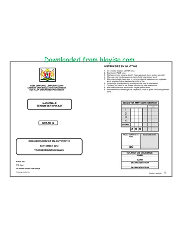
INSTRUCTIONS AND INFORMATION
1. The paper consists of FOUR questions.
2. Answer ALL the questions.
3. All drawings must be drawn to scale 1:1, unless otherwise stated.
4. The questions must be answered on the answer sheets provided.
5. All the answer sheets must be re-stapled in numerical sequence and
handed in irrespective of whether the question was attempted or not.
6. Careful time management is essential in order to complete all the questions.
7. Print your name in the block provided on every answer sheet.
EASTERN CAPE EDUCATION DEPARTMENT 8. All answers must be drawn accurately and neatly.
9. Any details or dimensions not given must be estimated in good proportion.
FOR OFFICIAL USE ONLY
MODERATED
NATIONAL MARK
SENIOR CERTIFICATE 1
2
3
4
TOTAL
GRADE 12
2 0 0
FINAL CONVERTED CHECKED BY
MARK
ENGINEERING GRAPHICS AND DESIGN P2
100
SEPTEMBER 2012
PREPARATORY EXAMINATIONS COMPLETE THE FOLLOWING:
NAME
NAME
MARKS: 200 EXAMINATION CENTRE
TIME: 3 hours EXAMINATION CENTRE
This question paper consists of 6 pages.
Copyright reserved Please turn over 1
Skip to contentAll 2012 papers 
View all





Engineering Graphics and Design Grade 12 P2 2012 QP (Eng)
Grade 12 Engineering Graphics and Design Paper 2 question paper from the Eastern Cape Mock Exam 2012 (English), 6 pages. Read online or download the free PDF.
Engineering Graphic And Design · Grade 12 · Eastern Cape Mock Exam · 2012. Question paper, 6 pages. Read online or download the PDF.
- Subject
- Engineering Graphics and Design
- Grade
- Grade 12
- Document type
- Question paper
- Year
- 2012
- Exam period
- Eastern Cape Mock Exam
- Paper
- 2
- Curriculum
- CAPS
- Pages
- 6
- File size
- 1.3 MB
Free to read online, no sign-up needed
Loading document…
Loading document…
1 of 6
This exam
Eastern Cape Mock Exam 2012
- Paper 1Memo
- Paper 2Question paper · EngQuestion paper · AfrMemo · EngMemo · Afr
- Other filesQuestion paperQuestion paper (2)Question paper (3)Question paper (4)Question paper (5)Question paper (6)Question paper (7)Question paper (8)Question paper (9)Question paper (10)Question paper (11)Question paper (12)MemoMemo (2)Memo (3)Memo (4)
Questions in this paper
Document textSearch extracted text and jump to a page.
Downloaded from hlayiso.com
Engineering Graphics and Design/P2 Ns EC DBE/September 2012
Ls 144 QUESTION 1: ANALYTICAL (MECHANICAL)
st
3
Given:
Four parts of a torsion arm with a title block and a table of
questions.
Instructions:
Complete the table below by neatly answering the questions,
which all refer to the accompanying drawings and title block. [25]
SECTION AA
1 | By who was the drawing approved? 1
2| 2. | What SI unit is used for the dimensions? 1
| aj 3. | Whats the file name of this drawing? 1
4 | inwhich street is the manufacturing company situated? 1
° 5. | What is the tolerance allowed on the dimensions? 1
6 1
7 1
8 | Whatis the total length (C) of the arm? 1
4 9 | Determine the degree of the internal angle of the taper (D)? 1
10 | Determine the dimensions at E 1
KEY 032 x 10 11 | What type of section is shown on part 1? 1
s 42 | What type of section is shown on part 2 (SECTION AA)? 1
43 | What is the name of the part that will be used to ensure that part 4 will not 2
turn loose?
| 14 | What is the size of the chamfer on part 17 1
ol ose -
| 15 | What is the purpose of feature B? 2
al | 146 | Complete the parts list by printing the names for parts 3 and 4. 2
4 | | 17 | Insert the correct dimensions for part 3, 2
a | 4g |" the box below (ANSWER 18), draw, in neat freehand, the symbol for the a
\ 914 6x) projection system used.
45°x4
TOTAL 25
116
ANSWER 18
26/10/2011 RODNEY CHANGE SIZE OF THREADED HOLE A
ALL DIMENSIONS ARE IN MILLIMETRES. DATE CHANGED BY REVISION DESCRIPTION No
(IEE GR ERNIE DRAWN BY: RIAAN DRAWING SET NO, 2 OF 3 MATERIAL: CAST IRON & MILD STEEL _ _
‘SPECIFIED, TOLERANCES: - PARTS LIST
Sse DATE; 15/09/2011 FILE NAME: SE-25/2011 HEAT TREATMENT: NONE
20,25 CHECKED BY: TAN VICTORIA STREET PART QUANTITY MATERIAL
DIRK WELDING CRADOCK
ALL UNSPECIFIED RADI DATE: 28/09/2011 ENGINEERING 5880 1, SPINDLE 1 CAST IRON
_ APPROVED BY: ANDY wwendnweiicozs | 2. ARM ‘ MILD STEEL EXAMINATION NUMBER
DATE: 19/10/2011 3. 1 MILD STEEL
DRAWING PROGRAM:
AUTOCAD 20%" Sout TORSION ARM 7 1 MILD STEEL EXAMINATION NUMBER 2
Copyright reserve Please tum over
Downloaded from hlayiso.com
Engineering Graphics and Design/P2
Nsc.
EC DBE/September 2012
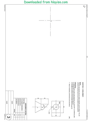
QUESTION 2: LOCI (CAMS)
Given:
* The shaft and follower detail of an industrial cam
with follower shown at its lowest posi
* The vertical centre line of the cam shaft as reference
on the drawing sheet.
The specifications for the movement are as follow:
«The cam shaft rotates anti-clockwise at constant
velocity
« Over the first 60° the follower rises 27 mm.
« There is a dwell period for the next 60°.
«Over the next 30° the follower rises a futher 28 mm
* There is a dwell period for the next 45°.
« Over the next 45° the follower drop 15 mm.
« — There is a dwell period for the next 45°.
* Over the final 75° the follower returns to its original
position.
Instruction:
2.1. Draw, to scale 1:1, the given view of the cam shaft
and follower using the vertical centre line as
reference. The arrow indicating the direction of
rotation must be shown.
2.2 Drawa displacement graph with a scale of 30° equal
to 10 mm and a follower displacement scale of 1:1
for the given motion. Label the graph.
2.3. Project and draw the cam profile that would generate
the given motion.
* Show ALL necessary construction. [38]
REFERENCE LINE —
CAM SHAFT AND FOLLOWER DETAIL
ASSESSMENT CRITERIA
1 GRAPH 10
2 FOLLOWER +SHAFT+ | 1.
ARROW + CLs.
3 CONSTRUCTION 4
4 CAM POINTS, 7
5 CURVE + QUALITY 7
TOTAL | 38
EXAMINATION NUMBER
EXAMINATION NUMBER 3
Copyright reserve
Please tum over
Downloaded from hlayiso.com
Engineering Graphics and Design/P2
Nsc.
EC DBE/September 2012
Loe
65.
30
QUESTION 3: ISOMETRIC DRAWING
Given:
© The front view, top view and left view of a s!
that is cut by cutting plane C-C.
* The position of point B on the drawing sheet.
ing jig
Instructions:
Convert the orthographic views of the sliding jig into a
scale 1 : 1 sectional isometric drawing on C-C.
© Make corner B the lowest point of the drawing so that
the sectional surfaces are visible.
© Show ALL necessary circle and other construction
[40]
30 40 15. |
ry
[.15_)
T
I
L
230
55
t
|
42
{60
20
80,
ASSESSMENT CRITERIA
1. AUX. VIEW+PLACING | 3
2. ISOMETRIC LINES 22
3, NONISOMETRIC LINES
cm
4, ISOMETRIC CIRCLES 5
5. CIRCLE CONSTRUCTION | 14
6. CENTRE LINES 2
7. HATCHING 1
TOTAL | 40
EXAMINATION NUMBER
EXAMINATION NUMBER [4
Copyright reserve
Please tum over
Engineering Graphics and Design/P2 Ns EC DBE/September 2012
QUESTION 4: MECHANICAL ASSEMBLY
en:
© The exploded isometric drawing of the parts of a
machine vice, showing the position of each part relative
to all the others.
* Orthographic views of each of the parts of the machine
vice.
Instructions:
«Answer this question on page 6.
* Draw, to scale 1: 1 and in third-angle orthographic
projection, the following views of the assembled parts
of the machine vice assemb
4.1 A sectional front view, on cutting plane A-A, as
seen from the direction of the arrow shown on the
exploded isometric drawing. The cutting plane is
shown on the top view of the base (part 1).
4.2 The top view.
* ALL drawings must comply with the guidelines
contained in the SABS 0111.
NOTE:
The jaws of the vice must be drawn 55 mm apart in the
open position.
* Show three faces of the M10 nu
* No hidden detail is required
the front view.
Add the following features to the drawing:
© The cutting plane AA
Downloaded from hlayiso.com
« Label the sectional view: SECTION A-A [97]
PARTS LIST
PART QUANTITY MATERIAL
1. BASE 1 CAST IRON
2. SHAFT 1 MILD STEEL
3. SLIDING BLOCK 1 CAST IRON
4, ROTATING BLOCK 1 CAST IRON
5. M10 SCREW 1 MILD STEEL
6. JAWS 2 MILD STEEL
7. MG SCREW 4 MILD STEEL
8. WASHER 1 MILD STEEL
EXPLODED ISOMETRIC
9. M10 NUT 1 MILD STEEL
DRAWN BY: Li54 KALIKA STREET
CHECKED BY: rons www.meeng.co.za
DATE: 20/09/20 THe
ALL UNSPECIFIED
RADII ARE R3 APPROVED BY. PIERRE MACHINE VICE
DATE: 197107 EASTERN CAPE
RAM DEPARTMENT BASIC EDUCATION e4
SCALE 1:2 GRADE 12 SEPTEMBER 2012 [5]
Copyright reserve Please tum over
Downloaded from hlayiso.com
Engineering Graphics and Design/P2
Nsc.
EC DBE/September 2012
ASSESSMENT CRITERIA
TOP VIEW
1. BASE
2. SHAFT
3. ROTATING BLOCK
4, M10 SCREW
5, WASHER
6. M10. NUT
7. CENTRE LINES
SECTION AA
SUBTOTAL
a
SECTIONAL FRONT VIEW
THIRD ANGLE
1. BASE
2. SHAFT
3, SLIDING BLOCK
4, ROTATING BLOCK
5. M10 SCREW
6. JAWS
7. WASHER
7
8. M10 NUT
9. CENTRE LINES
10. HATCHING
11. LABEL
SUBTOTAL
TOTAL
97
EXAMINATION NUMBER
EXAMINATION NUMBER
Copyright reserve
Study this subject
Recommended for this subject
Question paper
Engineering Graphics and Design Grade 12 2012 QP
Question paper
Engineering Graphics and Design Grade 12 2012 QP
Question paper
Engineering Graphics and Design Grade 12 2012 QP
Question paper
Engineering Graphics and Design Grade 12 2012 QP
Question paper
Engineering Graphics and Design Grade 12 2012 QP
Question paper
Engineering Graphics and Design Grade 12 2012 QP
More from Grade 12 Engineering Graphics and Design
Memorandum
Engineering Graphics and Design Grade 12 P1 2025 Memo
Memorandum
Engineering Graphics and Design Grade 12 P2 2025 Memo (Eng)
Memorandum
Engineering Graphics and Design Grade 12 P2 2025 Memo
Memorandum
Engineering Graphics and Design Grade 12 P2 2024 Memo (Eng)
Memorandum
Engineering Graphics and Design Grade 12 P1 2023 Memo (Afr)
Question paper