
basic education
Department
« y) Basic Education
"4 REPUBLIC OF SOUTH AFRICA
SENIOR CERTIFICATE EXAMINATIONS/
NATIONAL SENIOR CERTIFICATE EXAMINATIONS
INSTRUCTIONS AND INFORMATION
This question paper consists of FOUR questions.
Answer ALL the questions.
ALL drawings are in first-angle orthographic projection, unless otherwise stated.
ALL drawings must be prepared using pencil and instruments, unless otherwise
stated.
ALL answers must be drawn accurately and neatly.
ALL the questions must be answered on the QUESTION PAPER, as instructed.
ALL the pages, irrespective of whether the question was attempted or not, must
be re-stapled in numerical sequence in the TOP LEFT-HAND CORNER ONLY.
8. Time management is essential in order to complete all the questions.
9. Print your examination number in the block provided on every page.
10. Any details or dimensions not given must be assumed in good proportion.
BONS
Non
ENGINEERING GRAPHICS AND DESIGN P1
2021
MARKS: 100
TIME: 3 hours
This question paper consists of 6 pages.
| |
| |
| |
| Barcode label |
| |
| |
| |
FOR OFFICIAL USE ONLY
question | marks osTaeo | } | sic} moveraten | } | sion] Re-MARKING | } | sicn
1
2
3
4
TOTAL
2/0|0 2|0|0 2|0/0
FINAL CONVERTED MARK CHECKED BY
100
COMPLETE THE FOLLOWING:
CENTRE NUMBER
CENTRE NUMBER
EXAMINATION NUMBER
Copyright reserved
EXAMINATION NUMBER
Please tum over
Skip to contentAll 2021 papers 
View all





Engineering Graphics and Design Grade 12 P1 NSC June 2021 QP
Grade 12 Engineering Graphics and Design Paper 1 question paper from the NSC June Exam 2021 (English), 6 pages. Read online or download the free PDF.
Engineering Graphic And Design · Grade 12 · NSC June Exam · 2021. Question paper, 6 pages. Read online or download the PDF.
- Subject
- Engineering Graphics and Design
- Grade
- Grade 12
- Document type
- Question paper
- Year
- 2021
- Exam period
- NSC June Exam
- Paper
- 1
- Curriculum
- CAPS
- Pages
- 6
- File size
- 2.0 MB
Free to read online, no sign-up needed
Loading document…
Loading document…
1 of 6
This exam
NSC June Exam 2021
Questions in this paper
Document textSearch extracted text and jump to a page.
a Downloaded from hlayiso.com sc
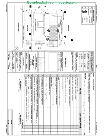
QS ¢ | LAND SURVEYOR'S CERTIFICATE FOR | SYMBOL LEGEND: Nore te verify all d 4 QUESTION 1; ANALYTICAL
Oe STAND 1232 contractors must verify all dimensions anc
S| eORNERHEIGHTS BOUNDARY LENGTHS) 1. DECIDUOUS TREES e levels on site before commencing work | Given:
IN METRES IN METRES Architects to be notified immediately of any " nts . . a
discrepancies. The site plan of an existing house with a proposed new lapa, a title panel and a table of questions. The drawing is not
A= 307.3 AB = 24,77 2. SHRUBBERY presented to the indicated scale.
B= 3075 BC = 48
c= 3048 077 3. SEALEOGARDEN > ARCHITECT'S SIGNATURE: Instructions: ; ;
LIGHTS anow Complete the table below by neatly answering the questions, which refer to the accompanying drawing, title panel and
D = 304,3 5,65 CLIENT'S SIGNATURE: civil content. [30]
A STAND 1291 8 ANSWER 20 QUESTIONS ANSWERS
In the space below, draw, in neat . blo for?
1600 BL freehand, the top view of the SANS 1 ]What was Sheila responsible for? 1
307 10143 graphical symbol for a 2 |Who printed the drawing? 1
— GREASE TRAP. >
|Z} beMousH 3 |What is the date of the second revision’ 1
EXISTING is indi ?
Sanne 4 |What scale is indicated for the drawing 1
Rel 5 |What is the web address of the architectural firm? 1
4m MOTOR VEHICLE io 6 | How wide is Ridge Road in millimetres? 1
ENTRANC! 1)
~ 7_|In which street is the main access to STAND 1232? 1
fa
= | 8 |How many sealed garden lights are shown on STAND 1232? 1
4x OW x In which two metric units are the dimensions on the site plan
3 Te g |} ne 2
8 FA indicated?
306 awow & | 19 | How should the garage have been presented to show that it has q
5 | to be demolished?
- | 11 |What does the arrow at 1 indicate? 1
' 12 |Name the symbol at 2. 1
fal 'E|
s H 13 |What does the abbreviation SWD at 3 stand for? 1
E | 3 14 |What is the abbreviation for the sewerage feature at 47 1
ele r —
Gh |B | -11-1| ADD STORMWATER What colour could be used to indicate new steel work on
e |2 al 2 [PPO] PIPE AND ORAIN | *® | elevations? 1
mf 2 al 1 [2020-11-17] Remove GARAGE | 16 |Which elevation of the existing house faces Staple Street? 2
a : ,
z EXISTING HOUSE i REVISION | DATE DESCRIPTION | 47 What isthe fall of STAND 1232 from corner A to comer D in :
me DRULOFF : - ‘i
of ARCHITECTS 18 |In the space below (ANSWER 18), determine the perimeter of STAND 1232 in metres. 3
sos ra etree oe 49 || the space below (ANSWER 19), determine the total area of the existing house in square metres. 7
“ a ae Round off the answer to TWO decimal places.
INK-ON (PTY)LTD | 2020-12-28 9 | In the space in the fille panel (ANSWER 20), draw, in neat freehand, the top view ofthe SANS 10743 |
DRAWING THLE graphical symbol fora GREASE TRAP
TOTAL | 30
SITE PLAN
ANSWER 18 ANSWER 19
PROIECT Show ALL calculations. amy Show ALL calculations.
PROPOSED NEW LAPA FOR PETER -—
PARKER ON STAND 1232, S| 6000
4 STAPLE STREET, PLETTENBERG BAY, at 4
4091 g
PROIECT NUMBER DRAWING NOWBER 8
® / e ‘RY-2020 8225 6000
so t DATE DRann — [ereoxeD, | SALE
~ RIDGE ROAD 6 m WIDE 2020-11-18] SHEILA CRISPIN 1:300 S| 3
—-—-—-—- -—-— REFERENCE CODE: 3 3g
SITE PLAN | SPDR-2020 EXAMINATION NUMBER
SCALE 1 : 300 or) EXISTING HOUSE EXAMINATION NUMBER [2
100000
Copyright reserved Please tum over
Engineering Graphics and Design/P1
DBE/2021
Downloaded from hlayiso.com
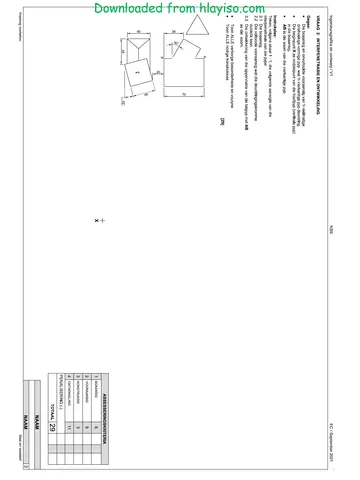
QUESTION 2: SOLID GEOMETRY
Given:
© The front view of a right regular hexagonal prism
with a right conical hole
© Anauxiliary view
* Horizontal cutting plane C-C
Instructions:
Draw, to scale 1 : 4, the following views of the solid:
2.1. The given front view
2.2 Asectional top view
2.3. The right view
© Planning is essential
* Show ALL hidden detail.
Show ALL construction.
[36]
ASSESSMENT CRITERIA
AUXILIARY VIEW 2
FRONT VIEW 5
eles
SECTIONAL TOP VIEW 16
4 |RIGHT VIEW 13
PENALTIES (-)
TOTAL} 36
EXAMINATION NUMBER
EXAMINATION NUMBER
[3
Copyright reserved
Please tum over
Engineering Graphics and Design/P1
PP.
Downloaded from hlayiso.com
DBE/2021
QUESTION 3; PERSPECTIVE
Given:
Three views of a modern exhibition centre and
the information needed to draw a two-point
perspective drawing
PP - Picture plane
HL - Horizon line
GL - Ground line
SP - Station point
Instructions:
Complete the perspective drawing.
© Align the drawing sheet with the ground
line (GL).
« Determine and label the vanishing points.
Show ALL construction.
« Show ALL visible internal detail as seen
through the opening and the glass
* NO hidden detail is required
[39]
ASSESSMENT CRITERIA
CONSTRUCTION 6
LOWER SECTION 15
HL—
a
a
OPENING <
co}
GL—
UPPER SECTION 6
1
2
3
4
ROOF
5
JARC
PENALTIES (-)
TOTAL | 39
HL
| OPENING
GLASS.
Copyright reserved
er
EXAMINATION NUMBER
EXAMINATION NUMBER
[4
Please tum over
Engineering Graphics and Design/P1
Downloaded from hlayi
|
ROOF CAP
RIDGE COVER
150 x 100 mm GUTTER ON
250 x 20 mm FASCIA BOARD
WITH @100 mm RWDP THAT
STOPS 50 mm ABOVE THE
GROUND LEVEL
3100
2050]
mal
RWVOE, 71
ROOF LINE
INCOMPLETE SCHEMATIC DIAGRAM OF
AROOF TRUSS AT CUTTING PLANE A-A,
ROOF NOTES:
30° ROOF PITCH
115 x 40 mm ROOF TRUSSES ON
145 x 40 mm WALL PLATES
300 mm ROOF OVERHANG TO END OF
ROOF TRUSS
20 mm FIBRE CEMENT ROOF SHEET ON
75 x 50 mm PURLINS @ 800 mm cic
250 x 20 mm FASCIA BOARDS WITH
150 x 100 mm GUTTERS ON ALL SIDES
10 mm CEILING BOARD ON 40 x 40 mm,
BRANDERING STRIPS @ 400 mm cle
s|s
1
i
i
v
WINDOW OPENING
FINISHED FLOOR LEVEL
GROUND LEVEL
‘SLIDING DOOR OPENING
250 x 150 mm STEP
FEATURES
D1 SLIDING DOOR
D2 DOOR
wW1 WINDOW
w2 WINDOW
w3 WINDOW
FIXTURES
we TOILET
WB WASH BASIN
B BATH
S SINK
ELECTRICAL FITTINGS
1. ONE-WAY SWITCH -
SINGLE-POLE
2. ONE-WAY SWITCH -
DOUBLE-POLE
CEILING LIGHT
WALL MOUNTED LIGHT
SWITCHED SOCKET OUTLET
owas
NOTE:
‘THE ARROW SHOWS THE LIGH
CONNECTION TO THE SWITCH.
ag
fu
3080
2080
GROUND
LEVEL
80 x 200 mm LINTELS
-— ABOVE ALL WINDOW
OPENINGS.
TOP OF
COURTYARD
2 | ‘
l
ROOM AND AREA DESIGNATIONS.
FLOOR FINISHES
1 BEDROOM: VINYL
2 BATHROOM: THLE
3 LIVING AREA: TILE
4 COURTYARD: PAVING
DOOR AND WINDOW SCHEDULE
a 1800. y p TOFIT 1 450
t 1
a 1500 y
1200
>
>
‘WINDOW (W1)
2050
2050
——
‘SLIDING DOOR (01)
sod]
WINDOW NOTES:
FLUORESCENT LIGHT 2 x 40 W * A= OPENING SIDE
* B= FIXED PANEL
* ALL FRAMES 50 mm THICK
WINDOWS
DOOR (02)
* 150 x 20 mm FIBRE CEMENT SILL UNDER ALL
F 1200 {00 |
Al
900
©
>
600
WINDOW (W3)
WINDOW (W2)
T ROOF COMPONENTS
ELECTRICAL SYMBOLS
— 250 x 20 mm FASCIA BOARD
A «16 6
150 x 100 mm GUTTER
= ie ¢oa
a 75 x 50 mm PURLINS
300
PN ROOF CAP AND RIDGE COVER
K xX ow!
WALL
RAINWATER,
FIXTURES
ITEMS.
80 mm
BRICK PAVING
ail,
sommcoupacteo J
HARDCORE
700
800
a
INCOMPLETE FOUNDATION
AND EXTERNAL WALL DETAIL
600
800
400
ry
eel
8) S
“letoor LEVEL Sj}
500
Or 3
(OF 8
750
200,
700
500
C3
100
WASH BASIN
(WB)
TOILET
(we)
1700
BATH
(8)
Copyright reserved
QUESTION 4: CIVIL DRAWING
Given:
* The incomplete north elevation of a new house, showing the
walls, the window opening, the sliding door opening, the roof
and labels
* The incomplete floor plan showing the walls, positions of the
doors, windows, fixtures and electrical layout
* An incomplete schematic diagram of a roof truss at cutting
plane A-A and roof notes
* The incomplete foundation and external wall detail
* Room and area designations and floor finishes
* A door and window schedule
* A table of roof components
* A table of electrical symbols
* A table of rainwater items
* A table of fixtures
* The incomplete floor plan and ground level of the new house,
drawn to scale 1 : 50, and the incomplete foundation and
break lines of a detailed section, drawn to scale 1 : 20, on
page 6
Instructions:
Answer this question on page 6.
4.1 Using the given incomplete floor plan and ground level,
draw, to scale 1 : 50, the following views of the new house:
4.1.1 THE COMPLETE FLOOR PLAN
Add the following features to the drawing:
* ALL doors and windows
* ALL fixtures as indicated by abbreviations
* ALL electrical fittings as indicated by numbers
* ALL hatching detail
4.1.2 THE COMPLETE NORTH ELEVATION
Show the following features on the drawing:
* The outside walls, step, window and sliding door detail
* The roof detail, including the fascia boards, gutters and
rainwater down-pipes
* The finished floor level
4.2 Using the incomplete foundation, draw, to scale 1 : 20 and
between the break lines, the DETAILED SECTION on
cutting plane A-A of the area in the ellipse shown on the
incomplete floor plan.
Show the following features on the drawing:
*The paving, complete foundation, external wall and
window detail
* The courtyard wall to the east of cutting plane A-A
* The roof detail, including all roof and rainwater items to
the east of cutting plane A-A
* ALL hatching detail. ONLY the substructure hatching may
be drawn in neat freehand.
Label the following:
* The north elevation
* The room designations and floor finishes
* Ground level, finished floor level and damp-proof course (use
the correct abbreviation and show it on ALL relevant views)
NOTE:
ALL drawings must comply with the guidelines and graphical
symbols as contained in the SANS 10143. [95]
[5
Please tum over
a Downloaded from hlayiso.com sc
De Sn ee Co FOR OFFICIAL USE ONLY
Og ROR INCORRECT SCALE(S)
3
A USED
B NON-ALIGNMENT OF
¢ Views
D VIEW(S) ROTATED
E SECTION VIEWED
F INCORRECTLY
c INCORRECT LETTERING
H
TOTAL ToTAL|
ASSESSMENT CRITERIA
GL_ FLOOR PLAN
possieie | osraneo | sign MODERATED]
ee
2 |rixrures 8
3 leectaca. at
4 |HaTcHING 3
5 |ussets 4
SUBTOTAL 363
NORTH ELEVATION
Ww 4 |ROoF + RwoP ai
Zz se
2 2 famusester= |g
Sg 3 |poor+wnoow | 8
x
4 |Laeets 1
SUBTOTAL 244
rs DETAILED SECTION
4 |rooroem | 144
3 farce 63
4 |soes 13
RWDP ‘SUBTOTAL 34
aa TOTAY 95
| PENALTIES (-)
| GRAND TOTAL
SECTION A-A EXAMINATION NUMBER
SOME ray V7 SCALE 1:20
|_ i | 6
Study this subject
Recommended for this subject
Question paper
Engineering Graphics and Design Grade 12 P1 NSC June 2021 QP
Question paper
Engineering Graphics and Design Grade 12 P1 2021 QP (Afr)
Question paper
Engineering Graphics and Design Grade 12 P1 NSC June 2018 QP
Question paper
Engineering Graphics and Design Grade 12 2021 QP
Question paper
Engineering Graphics and Design Grade 12 2021 QP
Question paper
Engineering Graphics and Design Grade 12 2021 QP
More from Grade 12 Engineering Graphics and Design
Memorandum
Engineering Graphics and Design Grade 12 P1 2025 Memo
Memorandum
Engineering Graphics and Design Grade 12 P2 2025 Memo (Eng)
Memorandum
Engineering Graphics and Design Grade 12 P2 2025 Memo
Memorandum
Engineering Graphics and Design Grade 12 P2 2024 Memo (Eng)
Memorandum
Engineering Graphics and Design Grade 12 P1 2023 Memo (Afr)
Question paper