
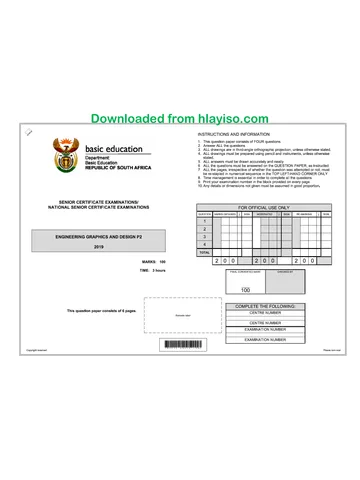
basic education
Department
« y) Basic Education
"4 REPUBLIC OF SOUTH AFRICA
NATIONAL
SENIOR CERTIFICATE
i ENGINEERING GRAPHICS AND DESIGN P2
i]
i NOVEMBER 2019
MARKS: 100
TIME: 3 hours
This question paper consists of 6 pages.
Copyright reserved
FOR OFFICIAL USE ONLY
QUESTION ]] MARKS OBTAINED | } | SIGN MODERATED | 3] SIGN RE-MARKING | 3] SIGN
1
2
3
.
1 4
1
i TOTAL
|
) 2])0/0 2/0/0 2])0/0
FINAL CONVERTED MARK CHECKED BY
100
oe _
INSTRUCTIONS AND INFORMATION
This question paper consists of FOUR questions.
Answer ALL the questions.
ALL drawings are in third-angle orthographic projection, unless otherwise stated.
ALL drawings must be prepared using pencil and instruments, unless otherwise
stated.
ALL answers must be drawn accurately and neatly.
ALL the questions must be answered on the QUESTION PAPER, as instructed.
ALL the pages, irrespective of whether the question was attempted or not, must
be re-stapled in numerical sequence in the TOP LEFT-HAND CORNER ONLY.
8. Time management is essential in order to complete all the questions.
9. Print your examination number in the block provided on every page.
10. Any details or dimensions not given must be assumed in good proportion.
ONS
NO
COMPLETE THE FOLLOWING:
CENTRE NUMBER
CENTRE NUMBER
EXAMINATION NUMBER
|
|
|
Barcode label |
|
|
|
EXAMINATION NUMBER
Please tum over
Skip to contentAll 2019 papers 
View all





Engineering Graphics and Design Grade 12 P2 2019 QP (Eng)
Grade 12 Engineering Graphics and Design Paper 2 question paper from the NSC November Exam 2019 (English), 6 pages. Read online or download the free PDF.
Engineering Graphic And Design · Grade 12 · NSC November Exam · 2019. Question paper, 6 pages. Read online or download the PDF.
- Subject
- Engineering Graphics and Design
- Grade
- Grade 12
- Document type
- Question paper
- Year
- 2019
- Exam period
- NSC November Exam
- Paper
- 2
- Curriculum
- CAPS
- Pages
- 6
- File size
- 1.6 MB
Free to read online, no sign-up needed
Loading document…
Loading document…
1 of 6
This exam
Questions in this paper
Document textSearch extracted text and jump to a page.
Engineering Graphics and Design/P2
Downloaded from hlayiso.com —
eo QUESTION 1: ANALYTICAL (MECHANICAL)
“gt
ay Given:
a Two views and a section of a mechanical jig, a title block and a table of questions. The drawing has not been prepared to
ol the indicated scale
stucs—~_| | | | | 2
~\ +
as Instructions:
’ Complete the table below by neatly answering the questions which refer to the accompanying drawing, the title block and
q mechanical content. [30]
- Rio) |
[—@ QUESTIONS ANSWERS
ANG 1 | What was Ingrid’s responsibility? 1
(Q) = 2 | What is the manufacturer's website address? 1
8 1 3 | Whats the file name? 1
M10 x 1,5 THREAD
- MIN 18 DEEP + 4 | Who is the client? 1
Rie 5 | How many jigs must be manufactured? 1
t
2) \ stone 6 | What is VIEW 1 called? 2
CBORE 016 x4 DEEP
7 | What type of section is VIEW R-R? 1
VIEW 2
8 | Name the type of section produced by cutting plane T-T. 1
=I 9 | Determine the complete dimensions at: A B: c: D: E: 5
2 10 | Determine the total length of the jig. 1
11 | Name the feature at F. 1
226 42 | What is the minimum depth of the thread required for the hole 1
at G?
7 13 | Name the feature at H. 1
{ o12)
8 a 44 | How many surfaces of the jig must be machined? 1
$3) al j : 15 | Describe the hatching mistake on VIEW 1 2
“tae ' Fl 46 | With reference to the tolerance, determine the minimum height q
t t at J.
VIEW R-R DIRECTION OF LAY
With reference to the machining symbol below, match the letter. [ROUGHNESS VALUE
17 | on the symbol with the correct label in the column to the right of 4
} 118 this question. SAMPLING LENGTH
154
MACHINING ALLOWANCE
VIEW 1 48 | In the space below (ANSWER 18), draw, in neat freehand, the symbol for the projection system used. | 4
TOTAL | 30
QUESTION 17. ‘ANSWER 18
FILE NAME: MJIG-12-V5 MATERIAL: CAST IRON POLISHED
QUANTITY: 30 UNITS FINISH; i
IG SCA \/
—_ . s NET? v b= POLISHED
IMMISSIONED BY: ALL DIMENSIONS ARE IN MILLIMETRES f)
JR MANUFACTURES: DRAWING AUTOCAD 2018 off) ee
105 FIRST AVENUE, BRITS PROGRAMME: ALL UNSPECIFIED RADII ARE 4mm. a
98 BROAD STREET | DRAWN BY: SIPHO DATE: 2018-11-13 ea /d
CASTFORM MIDDELFONTEIN
4070 CHECKED BY: INGRID DATE: 2018-12-14
ENGINEERING Se ee oe | APPROVED BY. NDING! DATE: 2019-01-21
E003 645 7820 EXAMINATION NUMBER:
TITLE
MECHANICAL JIG BB
EXAMINATION NUMBER
— a 0 I
Engineering Graphics and Design/P2
Se
DBE/November 2019
Downloaded from hlayiso.com
|
QUESTION 2; LOCI (CAM)
Given:
© The detail of a wedge-shaped follower and the
camshaft
© The position of centre point S on the drawing
sheet
Specifications:
¢ The follower reciprocates on the vertical centre
line of the camshaft
« The minimum distance from the follower to the
centre of the camshaft = 17 mm
Rotation = anti-clockwise
Motion:
The cam imparts the following motion to the
follower:
It descends 56 mm with uniform acceleration
and retardation over the first 180°
It rises 20 mm with uniform motion over the
next 45°
© There is a dwell period for the next 45°
* It returns to its original position with simple
harmonic motion over the rest of the rotation
Instructions:
* Draw, to scale 1: 1, the given camshaft and
the wedge-shaped follower at the minimum
distance.
* Draw to a rotational scale of 30° = 8 mm anda
displacement scale of 1 : 1, the complete
displacement graph for the required motion.
«Label the displacement graph and include the
scale
«Project and draw the cam profile from the
displacement graph.
* Show the direction of rotation on the cam
profile
* Show ALL construction and projection. [38]
th
FOLLOWER AND
CAMSHAFT DETAIL
Copyright reserved
ASSESSMENT CRITERIA
1 |Genmetnes | 8
2 | GRAPH CONSTRUCTION 7
3 | DISPLACEMENT GRAPH 9
4 | CAM CONSTRUCTION 6
8 5 | CAM+ CURVE QUALITY 1
PENALTY (-)
TOTAL | 38
EXAMINATION NUMBER
EXAMINATION NUMBER | 3
Please tum over
a Downloaded from hlayiso.com —
ae QUESTION 3; ISOMETRIC DRAWING
f
Given:
© The front view, top view and left view of
a tool jig
© The position of point P on the drawing sheet
Instructions:
Using scale 1 : 1, convert the orthographic views
of the tool jig into an isometric drawing.
* Make P the lowest point of the drawing
* Show ALL construction.
NO hidden detail is required. [41]
20 | 40 | | 304.20
{
iL! it sg
im
3
P | 20_|.20.|
_ 30
-20_| \ 60. al
rr
. 60" +
= ‘R20 2
7 ba g
20_/10) 10|_ 20, pP P 40 40
80 120
ASSESSMENT CRITERIA
1 | PLACEMENT + AUX. VIEW 3
2 =| FRONT PORTION 11
3. | BACK PORTION 213
4 [GonstRUCTION +L 54
PENALTIES (-)
TOTAL | 41
EXAMINATION NUMBER
EXAMINATION NUMBER 4
— ‘000000 0 ll
a Downloaded from hlayiso.com i
‘AN EXAMPLE OF THE CONVENTIONAL, QUESTION 4: ASSEMBLY DRAWING
8x @8 HOLES CSINK
REPRESENTATION OF A SPUR GEAR oy 2x1.5 DEEP
14 CSINK
™S_AT 90°
AT 90° TO B14
Given:
* The exploded isometric drawing of the parts of a gear and
sump assembly, showing the position of each part relative
to all the others.
* Orthographic views of each of the parts of the gear and
sump assembly
* An example of the conventional representation of a spur
gear
M8 SCREW [11]
Instructions:
* Answer this question on page 6.
© Draw, to scale 1: 1 and in third-angle orthographic
40 Ea projection, the following views of the assembled parts of
220 ind Tur I= the gear and sump assembly:
T 7 4.1 The half-sectional front view on cutting plane A-A.
os Show the left half in section, as seen from the
|-—_282 _.| direction of the arrow on the exploded isometric
| drawing. The cutting plane is shown on the top view of
+o —— the spur gear (part 3).
4.2 The top view. Show only the top half of the view by
B20
WASHER [2] | (222 | SeARS HAVE BEEN OMITTED applying the convention for the presentation of a
|- 282 | FOR PURPOSE OF CLARITY symmetrical object
NOTE:
* Planning is essential.
* ALL drawings must comply with the guidelines as
contained in the SANS 10111.
os © Show THREE faces of the M20 nut (part 1).
4 en © Draw the conventional representation of the spur gear
_————— ¥ Se = ef (part 3) in both views.
66 © NO hidden detail is required 193]
PIN [BI COLLAR [7]
Bx MB HOLES PARTS LIST
PART ‘QUANTITY MATERIAL
+ M20 NUT 1 MILD STEEL
a 2 | WASHER 1 MILD STEEL
e 3 | SPUR GEAR 1 CAST IRON
4 | SHAFT 1 CAST IRON
ie 5 |BusH 1 MILD STEEL
6 | COLLAR PLATE 1 MILD STEEL
SHAFT [4] 7 [cour 1 MILD STEEL
8 |PIN 1 MILD STEEL.
9 | SUMP. 1 CAST IRON
10 | PLUG 1 CAST IRON
11 | Ms SCREW 8 MILD STEEL
= 98 BROAD STREET
CASTFORM sanono sees
4070
ENGINEERING (PTY) LTD www foundry.co.za
ar GEAR AND SUMP ASSEMBLY
0)
v 52 PLUG [10] SUMP [9]
EXPLODED ISOMETRIC DRAWING ALL DIMENSIONS ARE| ALL UNSPECIFIED
Leased O00 00 0 000
Please tum over
a Downloaded from hlayiso.com —
Q3 FOR OFFICIAL USE ONLY
ge INCORRECT OVERALL SCALE
INCORRECT HATCHING
PARTS NOT ASSEMBLED
TOTAL PENALTIES (-)
ASSESSMENT CRITERIA
TOP VIEW
1 | GEAR 6
2 | COLLAR PLATE i
3 |Wwasher” | 43
4 | SYMMETRY 1
SUBTOTAL 12
SECTIONAL FRONT VIEW
4 | sump 165
2 | PLUG 7
3 |COLLARPLATE | 43
4 | BUSH 3
5 | COLLAR + PIN 5
6 | SHAFT 93
7 | GEAR 10
8 |Wwasner” | 62
9 | Ms scREW 6
SUBTOTAL 68
GENERAL
4 | CENTRE LINES 3
2 | ASSEMBLY 10
SUBTOTAL 13
TOTAL} 93
PENALTIES (-)
GRAND TOTAL
EXAMINATION NUMBER
— wv 000 0 aR Is
Study this subject
Recommended for this subject
Question paper
Engineering Graphics and Design Grade 12 P2 2019 QP (Afr)
Question paper
Engineering Graphics and Design Grade 12 P1 2019 QP (Afr)
Question paper
Engineering Graphics and Design Grade 12 P2 NSC June 2019 QP
Question paper
Engineering Graphics and Design Grade 12 P2 2023 QP (Afr)
Question paper
Engineering Graphics and Design Grade 12 P2 2023 QP (Eng)
Question paper
Engineering Graphics and Design Grade 12 P2 2022 QP (Afr)
More from Grade 12 Engineering Graphics and Design
Memorandum
Engineering Graphics and Design Grade 12 P1 2025 Memo
Memorandum
Engineering Graphics and Design Grade 12 P2 2025 Memo (Eng)
Memorandum
Engineering Graphics and Design Grade 12 P2 2025 Memo
Memorandum
Engineering Graphics and Design Grade 12 P2 2024 Memo (Eng)
Memorandum
Engineering Graphics and Design Grade 12 P1 2023 Memo (Afr)
Question paper