‘oon wd downloaded from hlayiso.com —_
» foe matters
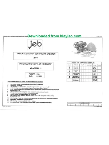
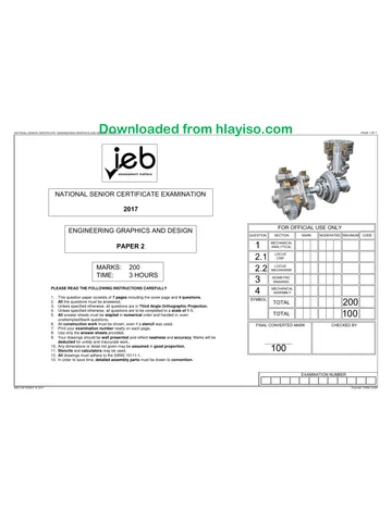
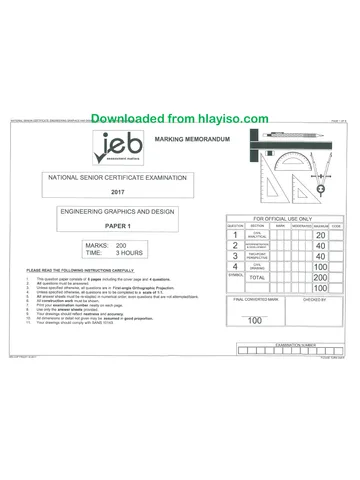
NATIONAL SENIOR CERTIFICATE EXAMINATION
2016
ENGINEERING GRAPHICS AND DESIGN
FOR OFFICIAL USE ONLY
PAPER 1 QUESTION || SECTION MARK —_||MODERATED||/MAXIMUM|| CODE
1 ANALYTICAL 20
MARKS: 200 DQ rasecensreaton 40
TIME: 3 HOURS 3 TWO-POINT 40
PERSPECTIVE
CIVIL
PLEASE READ THE FOLLOWING INSTRUCTIONS CAREFULLY 4 DRAWING 1 00
SYMBOL
1. This question paper consists of 6 pages including the cover page and 4 questions. TOTAL 200
2. All questions must be answered.
3. Unless specified otherwise, all questions are in First-angle Orthographic Projection. 1 00
4. Unless specified otherwise, all questions are to be completed to a scale of 1:1.
5. All answer sheets must be re-stapled in numerical order, even questions that are not attempted/blank.
6. All construction work must be shown. FINAL CONVERTED MARK CHECKED BY
7. Print your examination number neatly on each page.
8. Use only the answer sheets provided.
9. Your drawings should reflect neatness and accuracy.
10. All dimensions or detail not given may be assumed in good proportion. 1 (eye)
11. Your drawings should comply with SANS 10143.
EXAMINATION NUMBER.
IEB COPYRIGHT © 2016 PLEASE TURN OVER
You're offline
Skip to contentQuestion paper View all
EGD P1 2016 hlayiso.com
Electronic Graphics and Design · Grade 12 · 2016. Question paper, 6 pages. Read online or download the PDF.
- Subject
- Electronic Graphics and Design
- Grade
- Grade 12
- Document type
- Question paper
- Year
- 2016
- Paper
- 1
- Publisher
- IEB
- Pages
- 6
- File size
- 2.0 MB
Loading document…
Loading document…
1 of 6
Document textSearch extracted text and jump to a page.
‘oon od downloaded from hlayiso.com
PAGE 2 OF 6
QUESTION 1
ZG Architects CIVIL
“where the future is drawn" ANALYTICAL
TEL: 0213751244 12GREENRD P.O. BOX 768
15004800 FAX: 0213751245 CAPETOWN CAPE TOWN
wooden dock CELL: 083 1228122 2001 2000 STUDY THE ADJACENT DRAWING AND ANSWER THE QUESTIONS THAT FOLLOW:
Nose os www.zgarch.co.za
——= y design@zgarch.co.za
PRO TINS. | DRAWN BY: CHARLES SAMUELS. - -
guest sure MR WELLING, | CHECKED BY: SHIRLEY NAIDOO 1.1 What type of civil drawing is shown? 1
F APPROVED BY: A&B CONSULTANTS — -
carpet APPLE AVENUE DATE: 28 AUGUST 2012 1.2 How many bathrooms does this dwelling have? 1
WYNBERG __ || SIGNED: MR-T.K, MKIZE 1.3 What is the diameter of the ventilation pipe? 1
3 9 1.4 Who is the owner of the property ERF 572 1
* -_ | 4.5 In which city is the architect's office found? 4
2 =
y, of wm COL sow . 1.6 In which elevation would you see the main entrance door? 1
Se ve woos woos 1.7 What is the feature at 1 called? 1
SO 1.8 What is the feature at 2 called? 1
rope < PANTRY 1.9 What is the room designation indicated by the number 3? 1
‘ tes
LIBRARY 1.10 What does the abbreviation 'FP', as indicated at feature 4, stand for? 4
Oa caret Hl DINING ROOM 1.11 Suggest what the feature indicated by arrow 5 might be. 1
ies
MAIN ENTRANCE HALL _ 1.12 What is the feature at 6 called? 1
i les - 1.13 How many ND17 windows are shown on this drawing? 1
. le i ?
n —— | i 1.14 How many 40 watt fluorescent tubes are used in the kitchen’ 1
s ‘aToHEN 1.15 How many rooms have a tile floor finish? 1
tes | © 11.16 How many external doors are shown on this drawing? 1
5 | ounce BEDROOM 2 i e} 1.17 What type of brick must be used for the exterior walls? 1
2 vain carat q 1.18 What is the area of the wooden deck in square metres? 1
iN . 1.19 In the space below, draw, in NEAT freehand, the PLAN VIEW and ELEVATION VIEW
ON of the SABS convention for a wall-mounted urinal
BUILT-IN CUPBOARD \ PLAN VIEW ELEVATION VIEW
2
Mes
es
NOTES
Roof covering is to be clay tiles
—— —— Main bedroom sliding door must be
aluminium.
Exterior walls to be face brick
Interior walls to be standard clay brick.
20 MARKS
EXAMINATION NUMBER.
ANSWER SHEET 1
IEB COPYRIGHT © 2016
PLEASE TURN OVER
‘omens ed downloaded from hlayiso.com —
QUESTION 2
INTERPENETRATION|
& DEVELOPMENT
The figure below shows the INCOMPLETE Front View and
the INCOMPLETE Top View of a CIRCULAR PIPE
penetrated by an EQUILATERAL TRIANGULAR DUCT
drawn in First-angle Orthographic Projection. The auxiliary
view of the triangular duct is also shown in the Top View.
Draw the following:
2.1 the complete FRONT view clearly showing the curve
of interpenetration. Show all hidden detail.
2.2 the complete TOP view.
2.3 the development of the triangular duct.
Show all construction.
ASSESSMENT CRITERIA
You will be assessed on your ability to do the following:
* draw the given views 4
© complete the front view 7
* complete the top view 2
© show necessary construction 4
© develop and label the triangular duct 13,
80
0
pt @50
GW
4
FV,
7
Ww
2
[CON]
a
DEV]
3
40 MARKS
EXAMINATION NUMBER.
ANSWER SHEET 2
IEB COPYRIGHT © 2016
PLEASE TURN OVER
onsen de downloaded from hlayiso.com
PAGE 4 OF 6
y
QUESTION 3
TWO-POINT
PERSPECTIVE
The figure shows the three views of an apartment.
Draw a neat two-point perspective view of the
dwelling
PP _ - Picture Plane
HL - Horizon Line
GL - Ground Line
SP - Station Point
Show the wall thickness where applicable.
Neatly label the vanishing points RVP and LVP.
NO HIDDEN DETAIL IS REQUIRED.
ASSESSMENT CRITERIA
You will be assessed on your ability to do the following
* determine and label the vanishing points 2
* determine the two-point perspective view 38
PP PP
HL HL
GL
PTS|
23
PTS
Are
GL [ves]
Tee
40 MARKS
EXAMINATION NUMBER.
ANSWER SHEET 3
IEB COPYRIGHT © 2016
PLEASE TURN OVER
von sodas wod downloaded from hlayiso.com
SCHEMATIC SOUTH ELEVATION
TEXBO ¢
PURLINS =|
l@ 2000 ce
Corrugated asbestos = -— =
sheeting extends 65 mm|__
from the outer edge of \ 38X38
the purin bbranoeRINe
[2EX35) PearteNs
imate || @rs6.cc
/
EASCIA BOARD v
424_| 249
ROOF TRUSS DETAIL
———
§
A St
2.508
[FOUNDATION DETAIL | [DOOR DETAIL |
1080,
ey
GROUND LEVEL
‘al
l
200
1950
2040
600 DOOR
FRAME |
WINDOW DETAIL
22 CASEMENT
WOODEN wiNDOw 900
4150
L_. 4100 450
= Ta tt
a -GABt I
890
990
7
WINDOW FRAME
475 || 475
[aes ]]a75 | DOOR FRAME DETAIL
yanoow
FRAME,
3821
—— NY
E gl BE
g —_
7 | 260
i) FLOOR LEVEL avg O
—Z_ >= = = = = nN a
RotNOTEVEL
750, 1080, 5.170 400,600
poo El
T poor *
g : SHOWER
5 2
a g
2 600 rr}
FA pee a
s 3 ac |g
Z
tot 1150_| 675 | g
¥ 3
a 8 +
3) 2
= CUTTING PLANE
2760 2750
SCHEMATIC FLOOR PLAN
NOTES:
All windows are casement wooden frame windows.
PAGE 5 OF 6
ROOF DETAIL QUESTION 4
ROOF PROFILE CIVIL
DRAWING
Answer this question on ANSWER SHEET 4.
Use a scale of 1:50.
The following is given
* An incomplete schematic floor plan of a tiled GARDEN FLAT with
> window and door positions
> perimeter dimensions
* An incomplete schematic elevation with
> door and window positions, ground and floor levels
Incomplete foundation detail
Roof and roof truss detail
Plumbing fixtures legend
Window, window frame, window sill and door frame detail
Draw the following:
1) The complete floor plan
2) The SOUTH elevation showing the section as indicated by the cutting
plane A-A as well as the remaining outside elevation that is not cut.
FLOOR PLAN INSTRUCTIONS
© Draw and hatch all walls
Insert all window details and the door detail of the external door only
Draw the gully one brick course wide
Label the floor pian, scale, room designation and floor finish
Insert the following electrical detail
>A TWO, 40 watt fluorescent tube light in the middle of the room
one single pole light switch for the fluorescent light
> one switched socket outlet on the northern wall
* Insert the SANS plumbing symbols in the bathroom for the following:
> A water closet (toilet), shower and a wash basin as indicated
> Piping showing the basin and shower linking to the gully
. Draw the built-in cupboard
* Draw an external sewer line linking the given manhole to the toilet and
gully. Indicate a suitable rodding eye in your sewer configuration.
* Draw and label the cutting plane A-A
SECTIONAL SOUTH ELEVATION INSTRUCTIONS
* Draw the complete south elevation showing the section as per the
indicated cutting plane and the remaining outside elevation.
Show the outside C22 window
Show the extemal opening where the door frame would be positioned
Show some detail for the corrugated asbestos roof sheeting
Complete the foundation details
Draw all floor slab details
> use 10 mm screed and 150 mm compacted hardcore filing
Label the ground level and damp-proof course
* Draw in the sectional C22 window
> use ONE, 242 x 75 concrete lintel above the window
> use 222 x 110 quarry tile window sill
> show the window frame detail and label the damp proof course
© Roof details
> draw the roof truss using 114 x 38 rafters and 100 x 75 plates
> use FOUR, 76 x 50 purlins spaced at 2 000 centres
> use TWO, 121 x 38 wall plates
> use TWO, 38 x 38 battens spaced at 756 centres
> use 228 x 38 fascia boards
> use 9 mm gypsum ceiling boards
* Show all hatching detail and label the Sectional South Elevation
EXAMINATION NUMBER
IEB COPYRIGHT © 2016
PLEASE TURN OVER
on modummmmecesed downloaded from hlayiso.com —_
QUESTION 4
CIVIL
DRAWING
Assessment Criteria
[Sectional South Elevation
[Ceiling Battens 2
lWall Plates
[Ceiling Board
Truss Plates
Roof Truss
Purlins
Roof
\Walls
Window
0|Floor & Foundation
Ha[DPc
H12|Hatching 10
113[Fascia Board
14|Roof Detail
i15|Walls - elevation
H6|Labels
17|Outside window
©] |~[ola[ale [ny [=
nlolalals/salalals|n
rflalrlo lato
|18|External Door Position
Subtotal 61
Floor Plan
{1 9[External Plumbing
i20|Walls
l24|Hatching
l22|Windows
l23|Door
[24|Internal Plumbing
l25|Electrical
l26|Labels
l27|Cutting Plane
lz8|Cupboard
Subtotal 39
TOTAL __|100
nwiylalalolalalala[n
100 MARKS
EXAMINATION NUMBER
ANSWER SHEET 4
IEB COPYRIGHT © 2016
Recommended for this subject
Published documents with matching subject and grade metadata.
Related documents
Matched using subject, grade, language, document type and exam metadata.
More from Grade 12 Electronic Graphics and Design
Explore more published documents in this catalogue.