cou suanvonsmmeno egw nloaded from hlayiso.com
MARKING GUIDELINES.
eo
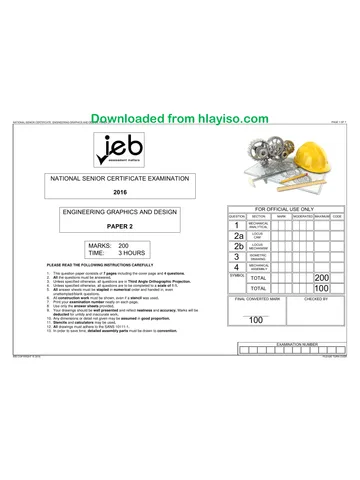
NATIONAL SENIOR CERTIFICATE EXAMINATION
PAGE 10F6
2019
ENGINEERING GRAPHICS AND DESIGN FOR OFFICIAL USE ONLY
MARKING GUIDELINES lauestion|| section || MARK _|/MopeRaTeo||Maximunl| CODE
PAPER 2 1 | anatercar 20
2 | 8 40
MARKS: 200 3 IsowerRc 40
TIME: = 3HOURS
4 | “sean 100
E READ THE Fe ING I CAREFULLY TOTAL 200
1 This question paper consists of 6 pages, including the cover page and 4 questions.
2. All questions must be answered,
3. Unless specified otherwise, all questions are in third-angle orthographic projection.
4. Unless specified otherwise, all questions are to be completed to a scale of 1:1.
5. All answer sheets must be re-stapled in numerical order and handed in, even
unanswered questions.
6. All construction work must be shown, even if a stencil was used.
7. Print your examination number neatiy on each page.
8. Use only the answer sheets provided.
9. Your drawings should be well presented and reflect neatness and accuracy. Marks
will be deducted for untidy and inaccurate work.
10. All dimensions or detail not given may be assumed in good proportion.
11. Stencils and calculators may be used.
12. All drawings must adhere to the SANS 10111-1.
13. In order to save time, detailed assembly parts must be drawn to convention.
EXAMINATION NUMBER
1EB COPYRIGHT © 2019 PLEASE TURN OVER
You're offline
Skip to contentQuestion paper View all
EGD P2 2019 hlayiso.com
Electronic Graphics and Design · Grade 12 · 2019. Question paper, 6 pages. Read online or download the PDF.
- Subject
- Electronic Graphics and Design
- Grade
- Grade 12
- Document type
- Question paper
- Year
- 2019
- Paper
- 2
- Publisher
- IEB
- Pages
- 6
- File size
- 3.2 MB
Loading document…
Loading document…
1 of 6
Document textSearch extracted text and jump to a page.
NATIONAL SENIOR CERTIFICATE: ENGINEERING GRAPHICS AND DNewniea d e d fro m h | ay i SO Cc Oo m
PAGE 2 0F 6
QUESTION 1
MECHANICAL
PART A
STUDY THE ADJACENT DRAWING AND ANSWER THE QUESTIONS THAT FOLLOW:
1.1 What does the abbreviation "NTS" stand for? NOT TO SCALE
1.2 What does the abbreviation "PCD" stand for? PITCH CIRCLE DIAMETER
1.3 Name the part that is manufactured from key steel? WOODRUFF KEY
1.4 What is the tolerance on all dimensions? 20,25
1.5 What are the maximum and minimum dimensions tolerated 52,25
at 4 in PartA? 51,75
1.6 What type of hole is shown at 2 in Part A? OIL / COUNTERSUNK HOLE
1.7 Name the type of sectioning at 3 in Part C.
REVOLVED SECTIONING
1.8 What is feature 4 in Part C called?
S-BREAK/ INTERRUPTED VIEW
1.9 What.is feature 6 in Part C called?
TAPER
1.10 What is feature 6 in Part D called? KEY WAY/KEY SLOT
1.11 Calculate the exact dimension at 7 in Part I. M20 x0.8 = 16
1.12 Name the type of sectioning in Part B. ALIGNED SECTIONING
1.13 What is the total height of Part A? 159
1.14 Which part prevents the coupling from sliding on the shaft? GRUB SCREW
PARTE PART F. PART © 1.15 In the space below, complete in freehand, the welding symbol indicating a square weld on site.
i WELDING SYMBOL
PART G PARTH PART J
7] ut) 1.16 In the space below, complete the machining symbo) Wine @ perpendicular direction of
a
lay using a grinding method to a surface roughness value
MACHINING SYMBOL
GRINDING
=_— — 0.2
MSIZA ENGINEERING - PARTS LIST
DESIGN / MANUFACTURE / ENGINEERING. [No] PART QUANTITY |___ MATERIAL |
244 INDUSTRIAL PARK TEL: 042 5551234 LA J_Housine IL_1___] cast iron __|
jervallal on eons path od B | COUPLING 4 |_CAST IRON
3655 www.msmzi.co.za C || SHAFT jE 4 MILD STEEL
info@msmz!.co.za D || GEAR 1 || STEEL
TITLE: E || BUSH 2___|| PHOSPHOR BRONZE
DRAWN BY: — P SWART
CHECKED BY: FREDDIE TSHABALALA\ INTERMEDIATE [_F || SPACER [4 | PHOSPHORBRONZE |
APPROVED BY: LECNARD MEYER SHAFT AND GEAR G | WASHER 4 | MILD STEEL ]
SIGNED: DEAN SING SCALE: NTS H] MizGRUBScREW || 14 | MILD STEEL |
‘ALL UNSPECIFIED RADII ARE R3. am) 1] mito STEEL |
TOLERANCES ON ALL DIMENSIONS ARE: 0,25 ak 4 KEY STEEL i)
EXAMINATION NUMBER
[J | |
Lit tT |
ANSWER SHEET 14
IEB COPYRIGHT © 2079
‘PLEASE TURN OVER
Downloaded from hlayiso.com
NATIONAL SENIOR CERTIFICATE: ENGINEERING GRAPHICS AND DESIGN: PAPER 2 — MARKING GUIDELINES PAGE 30F 6
QUESTION 2
LOCI
CAM
SEE The drawings show the following:
to A DISPLACEMENT GRAPHs * _ anincomplete graph of displacement in position of
Ey 2 a roller-ended follower.
— Ne Ty] = . the centre lines of a camshaft.
| ji ° the shaft and follower detail at the starting position.
#4 1+ _— ‘The cam imparts the follawing motion to the follower:
* — 0°— 60° the follower is at rest.
«| ¢ _ le * | |= 60°—120° the follower rises 28 mm with uniform
| motion.
jie 120° — 165° the follower is at rest.
f |e 465° — 255° the follower fats 56 mm with simple
harmonic motion.
. 255° — 300° the follower is at rest.
t iz « — 300°— 360° the fallower returns to its original
a ae Ae I position with uniform motion.
The cam profile has the following specifications:
© The direction of turn is clockwise.
¢ The camshaft has a diameter of 18 mm.
2.1 Draw and hatch the camshaft,
2.2 Draw the roller-ended follower to specification,
2.3 Draw the complete graph of displacement.
2.4 Draw the direction of rotation.
Sass 2.5 Draw and label all the divisions on the cam profile.
2.6 Draw the cam profile from the displacement graph.
2.7 Label the graph of displacement at A.
8 2.8 Show all constructions,
ASSESSMENT CRIT Ria.
5 + Graph & Label 1
» Plot Points 16
¢ Locus & Construction 4
| + Shaft and Hatching 2
~ x — ¢ Direction & Divisions 2
° Follower 1
o18
EXAMINATION NUMBER
EETLTITTETET TL I
EB COPYRIGHT © 2019 PLEASE TUN OVE
PAGE 4 OF 6
CONSTRUCTION AREA
ANSWER SHEET 3
QUESTION 3
DRAWING
plane A-A.
plane A-A,
other auxiliary views.
3.3 Draw the centre lines for the circle.
The drawings below show the front view, top view and
right view of a CASTING. The CASTING is cut by cutting-
3.1 Draw a néat full-sectioned isometric drawing
on cutting-; a
3.2 Show the construction for the square and any
3.4 Make point P the lowest part of your drawing.
3.5 Start your drawing on the given crosshairs.
EXAMINATION NUMBER
‘i I |
‘|
i [4
j |
|
5 ripe las}
a pog0p0
—
1 ROT 2
ee 4S)-
[Lt Jt ! 1 > |
i t=; ro H , > e
td J 30°
— + |
- “kA | ps, 8s | o
ae
IRC
gr ||
* Constructions 2
bonette Ponta, 402 20 ES [e |
* Isometric Circles 8 HAT
lon-I Lal
1 Hecae 7 alla
(EB COPYRIGHT ©2018
i
5
a
Downloa
ded from hlayiso.com
NATIONAL SENIOR CERTIFICATE: ENGINEERING GRAPHICS AND DESIGN: PAPER 2 — MARKING GUIDELINES
PAGE 5 OF 6
PART A
ed
i
i
1
L
'
'
t
eee
----------4
7
PART D
| wi2x2 TAPPED HOLE
248
24
M20 NUT
PART J
g
| R10
M12x2 GRUB SCREW
QUESTION 4
| MECHANICAL |
|_ASSEMBLY |
Figure 1 shows the different parts (not to scale) for an INTERMEDIATE
SHAFT AND GEAR that need to be assembled.
The exploded front view of how the parts are assembled is also shown.
Complete the following on Answer Sheet 4 to a scale of 1:7.
Use the given centre lines and point P on the shaft (Part C) as
a reference to plan the drawing layout.
4.1 Draw a half-sectional front view of the assembled parts on cutting
plane A-A. The top half (above the centre line of the shaft) must be
in section.
4.2 Draw a right view of the assembled parts, without the
coupling (Part B), on the given centre lines.
4.3 Please note the following:
4.3.1 Show 3 faces for the hexagonal nut in the front view.
4.3.2 Show the hidden detail of only the housing (Part A) in the
right view.
4.3.3 Draw the cutting plane and the missing centre lines.
4.3.4 Insert 3 functional dimensions in the right view.
4.3.5 Draw the projection symbol in the space provided.
4.3.6 Print the title and scale in the space provided.
4.3.7 Correctly label the completed front view.
4.3.8 The gear (Part D) must be drawn in convention.
PARTS LIST
PART
|LQuanTrTy ||
MATERIAL
| HOUSING
| 4 || CAST IRON
EXPLODED FRONT VIEW
|_ COUPLING
| 4 | CAST IRON
| SHAFT
4 | MILD STEEL
PARTS
| STEEL
38
J
J
|
]
J
PHOSPHOR BRONZE
| SPACER
PHOSPHOR BRONZE |
PARTS.
Pot 48
PARTS.
|| MILD STEEL
J
[|| Mi2GRUBSCREW __ |
|| MILD STEEL
_|
[1 || M20 HEXAGONAL NUT ||
|| MILD STEEL
_|
4
2
_| 4
G | WASHER 4
1
1
1
[J || WOODRUFF KEY ll
__|| KEY STEEL
EXAMINATION NUMBER
1EB COPYRIGHT © 2019
PLEASE TURN OVER
Downloaded from hla
NATIONAL SENIOR CERTIFICATE: ENGINEERING GRAPHICS AND DESIGN: PAPER 2 — MARKING GUIDELINES
yiso.com
PAGE 6 OF 6
v
4<
4
+ - Ht Zw
A la
wv
|
YY 4
\ y A on 1
al NAY a ee
C)
] 4
v NEY
SON: +
P Iv
A LJ
le
A
A A
A A
A
A
x
[SECTIONAL FRONT VIEW ON A-A/ SECTION A-A]
INTERMEDIATE SHAFT
TITLE:
AND GEAR SYMBOL;
SCALE: | scate 1:1
QUESTION 4)
FRONT VIEW
HOUSING
COUPLING
A
B
C|sHarT
D|cear
E
F
G
H
BUSHES
SPACER
WASHER
M12 SCREW
M16 NUT
KEY
OTAL|
>| ¥/4|O/Sm|@| </>|>
a]
RIGHT VIEW
A|HOUSING
C| SHAFT
D/GeAR
G| WASHER
M16 NUT
HIDDEN DETAIL 12/2
TOTAL |
SFO S| </>
ADDITIONA!
CORRECT ASS.
HATCHING 14/2
NON-HATCHING 4/2,
CENTRE LINES 8/2)
DIMENSIONS
CUTTING PLANE
SYMBOL
ANSWER SHEET 4
<i<[SalUl 40/5] 5
TITLE/SCALE/LABEL
TOTAL
TOTAL
EXAMINATION NUMBER
Tt. T 4
SS COPYRIGAT O201S
Recommended for this subject
Published documents with matching subject and grade metadata.
Related documents
Matched using subject, grade, language, document type and exam metadata.
More from Grade 12 Electronic Graphics and Design
Explore more published documents in this catalogue.