°
WG semen matters
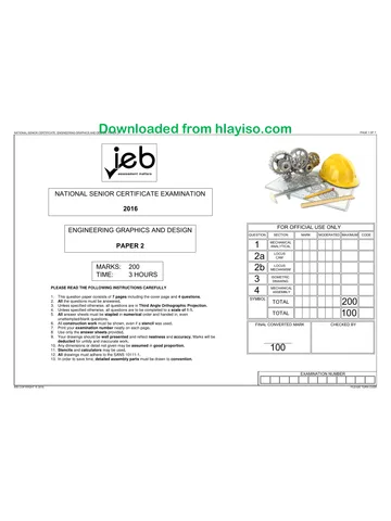
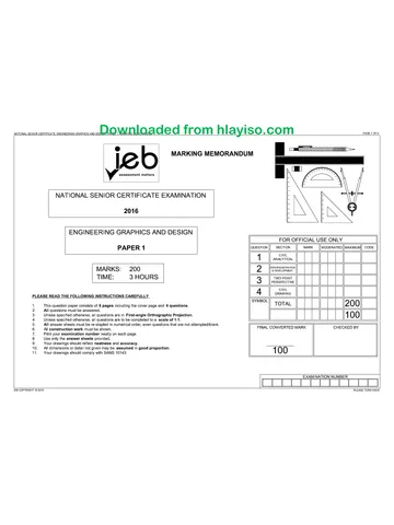
NATIONAL SENIOR CERTIFICATE EXAMINATION
2017
ENGINEERING GRAPHICS AND DESIGN
PAPER 1
MARKS: 200
TIME: 3 HOURS
PLEASE READ THE FOLLOWING INSTRUCTIONS CAREFULLY
This question paper consists of 6 pages including the cover page and 4 questions.
All questions must be answered.
Unless specified otherwise, all questions are in First-angle Orthographic Projection.
Unless specified otherwise, all questions are to be completed toa scale of 1:1.
All answer sheets must be re-stapled in numerical order, even questions that are not attempted/blank.
All construction work must be shown.
Print your examination number neatly on each page.
Use only the answer sheets provided.
Your drawings should reflect neatness and accuracy.
All dimensions or detail not given may be assumed in good proportion.
Your drawings should comply with SANS 10143.
$0) 00) Fal Gl Gon GI fo >
ms
PAGE 1 OF 6
<=
KX
TT TT
FOR OFFICIAL USE ONLY
1 aavtica 20
3 |pcrscconve 40
4 | oxawine 100
SYMBOL, TOTAL 200
100
FINAL CONVERTED MARK CHECKED BY
100
EXAMINATION NUMBER
IEB COPYRIGHT © 2017
PLEASE TURN OVER
You're offline
Skip to contentQuestion paper View all
EGD P1 2017 hlayiso.com
Electronic Graphics and Design · Grade 12 · 2017. Question paper, 6 pages. Read online or download the PDF.
- Subject
- Electronic Graphics and Design
- Grade
- Grade 12
- Document type
- Question paper
- Year
- 2017
- Paper
- 1
- Publisher
- IEB
- Pages
- 6
- File size
- 2.7 MB
Loading document…
Loading document…
1 of 6
Document textSearch extracted text and jump to a page.
°
SMITH, ZULU & Co ARCHITECTS
“designing the future”
P.O.BOX 1683 TEL: (044) 7612233 www.smithzulu.co.za 23 COPPER STREET
GEORGE FAX: (044) 7612234 office@smithzulu.co.za GEORGE
6530 CELL: 0837612233 info@smithzulu.co.za 6529
PROPOSED ADDITION FOR A.B. VILLIERS. DRAWN BY: PATRICK LOUW | DATE: 12 FEBRUARY 2017 lap = 3435 oe e700
GOLD STREET CHECKED BY: T.B. ZULU = a u
ERF 1100 APPROVED BY: H.V. SMITH aBVILLIERS 5000, DE
GEORGE SOUTH REFERENCE: {002/VILLIERS __| |SIGNED: MR A.B. VILLIERS
F = 22000, FA = 42000}
QUESTION 1
CIVIL
ANALYTICAL,
STUDY THE ADJACENT DRAWING AND INFORMATION AND ANSWER THE QUESTIONS THAT FOLLOW:
ERF 1102 (7) ©® ® ® 4.1 What type of civil drawing is shown? 1
i 1.2 What elevation faces the Gold Street? 1
ls 818 819, 1.3 Who checked the drawing? 4
H 2000 B/L 1.4 In which town is the architect's office located? 1
7 a a i / 1.5 On what erf number will the proposed additions be erected? 1
i) / 1.6 What is the feature at 1 called? 1
! | \_/ -{] w|_ [PRoPoseD 1.7 What is the feature at 2 called? 1
la S a x 1.8 What is the feature at 3 called? 1
lo . GARDEN lo i
3 <a FLAT is 1.9 What is the feature at 4 called? 1
IN ot fy 1.10 What is the feature at 5 called? 1
Hl J MH 1.11 What is the feature at 6 called? 1
exstncoweune / 7 > —-— 1.12 What is the feature at 7 called? 1
i Hl ! A 1.13 What is the feature at 8 called? 1
Z| /* DB 1.14 What is the feature at 9 called? 1
ol # | 1.15 Which direction would you face when reversing out of the garage? 1
3! ( 4 4.46 How many metres would Mr Villiers walk if he walked the boundary? 1
j ao ERF 1101 1.17 By how many metres is the highest corner above the lowest? h
| 1S
| PROPOSED | | = s 1.18 What is the closest Mr Villiers is allowed to build to Gold Street? 1
| At i 3 N 1.19 In the space below, determine the area of the proposed new garage in m?
| 1 y an
H 6000 | 4
i | 1
MH | Ny @
| 2
|
'
|
+ '
Answer:
i 1
|
1
ERF 1100
i 2000 BIL
i E 20 ‘s
| BIG ERF 1098 e16 MARKS
EXAMINATION NUMBER
ANSWER SHEET 1
1EB COPYRIGHT © 2017 PLEASE TURN OVER
ANSWER SHEET 2
°
QUESTION 2
INTERPENETRATION|
& DEVELOPMENT
The figure below shows the INCOMPLETE Front View and
the Top View of an EQUILATERAL TRIANGULAR DUCT
penetrated by an CIRCULAR PIPE drawn in First-angle
Orthographic Projection. The auxiliary view of the circular
pipe is also shown in the Top View.
Draw the following:
2.1 the complete FRONT view clearly showing the curve
of interpenetration. Show all hidden detail.
2.2 the complete TOP view.
2.3 the development of the two surfaces of the triangular
duct that are being penetrated, clearly showing the
curve of interpenetration.
Show all construction.
ASSESSMENT CRITERIA
You will be assessed on your ability to do the following:
*® — draw the given views 5
complete the front view 17|
* show necessary construction 3
« — develop and label the triangular duct. 15
iS
\
70
\
15
50
(CON)
DEV
15.
40 MARKS
EXAMINATION NUMBER
IEB COPYRIGHT © 2017
PLEASE TURN OVER
NATIONAL SENIOR CERTIFICATE: ENGINEERING GRAPHICS AND DE!
PAGE 4 OF 6
QUESTION 3
TWO-POINT
PERSPECTIVE
The figure shows the three views of an outside
entertainment area, which includes a braai.
Draw a neat two-point perspective view of this area.
PP - Picture Plane
HL - Horizon Line
GL - Ground Line
SP - Station Point
Neatly label the vanishing points RVP and LVP.
NO HIDDEN DETAIL IS REQUIRED.
ASSESSMENT CRITERIA.
You will be assessed on your ability to do the following:
ANSWER SHEET 3
* determine and label the vanishing points 2
* determine the two-point perspective view 38
PP. PP
HL HL
PTS)
19
PTS|
8
Con
tl 2
i Ke
4 g
t Hl | —_ GL [weg
H 2
GL
SP
40 MARKS.
EXAMINATION NUMBER
IEB COPYRIGHT © 2017
PLEASE TURN OVER
[ROOF DETAIL ] QUESTION 4
ROOF PROFILE DARING
‘Answer this question on ANSWER SHEET 4.
Use a scale of 1:50.
CORRUGATED The following is given:
Aces * Anincomplete schematic floor plan of a tiled LAUNDRY addition with
|_SHEETING |
> window and door positions
> perimeter dimensions
10X75 | * Anincomplete schematic elevation with
URUSSPLATE] | > door and window positions, ground and floor levels
FOOKSO “~ 2 * Incomplete foundation detail
PURLINS +| * Roof and roof truss detail
2560 on — EXISTING! © Window, window frame, window sill and door frame detail
Corrugated asbestos Z ——— * The existing wall to which the addition is attached
sheeting extends 65 mm featicliowdna:
TTontha outer edge of \ XH REMOVE THIS SECTION OF Draw the following: - - ;
the purln | | aacqq) BRANDERING WALL TO ALLOW ACCESS \ 1) The complete floor plan attaching your drawing to the given existing
i WALL | | BATTENS. 7 Ps. walls on answer sheet 4.
“ puate | |@ 44 | = 2) The SOUTH elevation showing the section as indicated by the cutting
a a tho ot
EAUUIA BAL soo_| 2a ol 3) The outside EAST elevation showing the laundry addition only.
2 e |
g 3 gg FLOOR PLAN INSTRUCTIONS
8 is s © Draw and hatch all walls
ROOF TRUSS DETAIL 260 * Indicate appropriately, the removed section of the existing wall
—F rooruever_| _ So © Insert all window details and the door detail
% coun sonce =v SE © Draw the gully
{GROUND LeveL * Label the floor plan and indicate the scale, room designation and floor
SCHEMATIC SOUTH ELEVATION finish ;
* Insert the following electrical detail: |
3679 >A TWO, 40 watt fluorescent tube light in the middle of the room
> one wall mounted light outside the door
[FOUNDATION DETAIL | [DOOR DETAIL | soco > one double pole light switch on the western wall for both the lights
> one switched socket outlet on the northern wall under the window
o 1080 _, p1150__, 687 1758 ‘* Insert the SANS plumbing symbol for the double sink unit
ot {WINDOW | © Draw and label the cutting plane A-A
7 | , ‘ al SECTIONAL SOUTH ELEVATION INSTRUCTIONS
| 8 + Draw the complete south elevation showing the section as per the
EXISTING indicated cutting plane
|@RouND LeveL el * Show the removed section of the existing wall
g| 7 | ul 5 © Show the outside C22 window
i 7 g | 3 * Complete the foundation details
a o) - sl > WALLTO BE REMOVED! : © Draw all floor slab details
= Door, | 3 | 4. _s_ > use 10 mm screed and 150 mm compacted hardcore filing
sco FRAME | Ey Va CuTTiING PLANE fe = © Label the ground level and damp-proof course
* Draw in the sectional door
WINDOW DETAIL i| amaowt > use ONE, 242 x 75 concrete lintel above the door
pa Hl 3 © Roof details:
WOODEN WINDOW 800 " 4 > draw the roof truss using 114 x 38 rafters and 100 x 75 plates
pe ue = ae > use THREE, 100 x 50 purl dd at 2 560 cent
™ use - x purlins spaced al centres:
4100 150 SCHEMATIC FLOOR PLAN > use ONE, 121 x 38 wall plate
Gost L__. > use TWO, 38 x 38 battens spaced at 1 253 centres
le =a > use a 228 x 38 fascia board
75 8) NOTES: > use 9 mm gypsum ceiling boards
wiNbow FRaMe Gully is 400 x 400, brick course thick and 2 bricks high. © Correctly position the SANS symbol for the double sink unit
— DOOR FRAME DETAIL All windows are C22. © Show all hatching detail and label the Sectional South Elevation
FRAME The floor must be tiled. EAST ELEVATION INSTRUCTIONS
- Place the double sink so that the top surface is $00mm from the floor. © Draw the complete outside east elevation showing the laundry only
re The double sink dimensions are 1660 long, 535 wide and 300 deep. ® Show some detail for the corrugated asbestos roof sheeting
* _ Indicate the Finished Floor Level and label the elevation
7“ EXAMINATION NUMBER
__|__t
IEB COPYRIGHT © 2077 PLEASE TURN OVER
ANSWER SHEET 4
°
EXISTING
FLoor evel |
EXISTING
PAGE 6 OF 6
QUESTION 4
CIVIL,
|_pRAWING _|
Assessment Criteria
Sectional South Elevation
|Ceiling Battens 2
Wall Plates
Ceiling Board
[Truss Plates
Roof Truss
[Purlins
[Roof
Walls
Door
10|Floor & Foundation
11|DPC & Labels
12[Hatching
13|Fascia Board
14|Outside window
115|Double Sink
Subtotal
Floor Plan
16|Plumbing
17|Walls
18|Hatching
19|Windows
[20|Door
21/Electrical
[22/Labels
|23|Cutting Plane
Subtotal 34
West Elevation
24|Walls & Gully
[25|Roof Detail
|26|Door
(27|Fascia Board
[28|Floor Finish Level
\29|Label
| Subtotal 16
TOTAL _|100
©]o[~lolalsfo[y]=
efaj=[wlofalalalslololala/=
a
8
vlalolalalelola
=u |plolylo
100 MARKS
EXAMINATION NUMBER
IEB COPYRIGHT © 2017
Recommended for this subject
Published documents with matching subject and grade metadata.
Related documents
Matched using subject, grade, language, document type and exam metadata.
More from Grade 12 Electronic Graphics and Design
Explore more published documents in this catalogue.