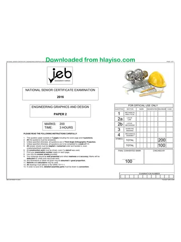
NATIONAL SENIOR CERTIFICATE EXAMINATION
2019
ENGINEERING GRAPHICS AND DESIGN
PAPER 1
MARKS: 200
TIME: 3 HOURS
PLEASE READ THE FOLLOWING INSTRUCTIONS CAREFULLY
PAGE 1 OF 6
INN
i FOR OFFICIAL USE ONLY
fauestion | secrion | war _ |/mobeRaTED [axa] aa]
1 | wines 20
2 precesmere 40
3 renspecive 40
4 | athe 100]
1. This question paper consists of 6 pages including the cover Page and 4 questions. TOTAL 200
2. Ail. questions must be answered. SO
3. Unless specified otherwise, all questions are in First-angle Orthographic Projection. CHECKED BY
4. Unless specified otherwise, all questions are to be completed toa scale of 1:1.
5. All answer sheets must be re-stapled in numerical order, even questions that have not been answered.
6. All construction work must be shown.
7. Print your examination number neatly on each page.
8. Use only the answer sheets provided.
9. Your drawings should reflect neatness and accuracy.
10. All dimensions or detail not given may be assumed in good proportion,
11. Your drawings should comply with SANS 10143.
| I T Cee T |
PLEASE TURNOVER:
1EB COPYRIGHT © 2019,
You're offline
Skip to contentQuestion paper View all
EGD P1 2019 hlayiso.com
Electronic Graphics and Design · Grade 12 · 2019. Question paper, 6 pages. Read online or download the PDF.
- Subject
- Electronic Graphics and Design
- Grade
- Grade 12
- Document type
- Question paper
- Year
- 2019
- Paper
- 1
- Publisher
- IEB
- Pages
- 6
- File size
- 476.6 KB
Loading document…
Loading document…
1 of 6
Document textSearch extracted text and jump to a page.
ERF 4199
SO
f
\
-" f,
\S
4
EXISTING
RETIREMENT
O
\
\
\
/ PROFOSED
NEW
UNIT
if
7 (
1 lPROPOSED
aN NEW
\ UNIT
ERF 5199 \O /]
|PROPOSED}
NEW
UNIT
NATURE
RESERVE
PROPOSED}
NEW
UNIT
|
|
|
UNIT 3
i
| ff
/
> \ Jf 1105,
/
ERF 5201
SCALE 1:500
PAGE 2 OF 6
QUESTION 1
CIVIL
ANALYTICAL
STUDY THE ADJACENT DRAWING AND ANSWER THE QUESTIONS THAT FOLLOW:
[1.1 What type of civil drawing is shown?
[1.2 Which ERF is to the NORTHEAST of the retirement complex?
1.3 How many manholes are there in this drawing?
/1.4 Which corner has the lowest elevation? (either A,B,C,D,E or F)
1.5 How many trees need to be removed?
11.6 What is the feature al 1 called?
1.7 What is the feature at 2 called?
1.8 What is the feature at 3 called?
1.9 What is the feature at 4 called?
1.10 What is indicated at feature 5?
1.11 Has the ramp been drawn correctly?
1.12 What is the feature at 6 called?
[1.13 What Is the feature at 7 called?
1.14 What is the feature at 8 called?
1.15 in what colour would a proposed new unit be drawn on this plan?
/1.16 Is this drawing drawn to the scale indicated?
1.47 What does the abbreviation IE stand for?
1.18 What is the closest that a new unit can be placed to ERF 5200?
11.19 In the space below, determine the area of the Frail Care Centre in m+
ANSWER SHEET 1 | | | | |
EXAMINATION NUMBER
IEB COPYRIGHT © 2019
PLEASE TURN OVER
NATIONAL SENIOR: CERTIFICATE; ENGINEERING: GRAPHICS: AND DI
ANSWER SHEET 2
PAGE 3 OF 6
QUESTION 2
The drawings below show the COMPLETE Top and Right
View as well as the INCOMPLETE Front View of a
CYLINDRICAL PIPE which has been joined together with
a SQUARE DUCT and drawn in First-angle Orthographic
Projecton. An Auxiliary View of the square duct is also '
shown in the Top and Front Views.
Draw the following:
2.1 the complete Front View clearly showing the curve
of interpenetration. Show all hidden detail.
2.2 the development of only half of the cylindrical pipe
which joins with the duct, clearly showing the curve of
interpenetration.
‘Show all construction and calculations.
Do not draw the right view.
The complete Top View and an Auxiliary View have
already been drawn in position.
ASSESSMENT CRITERIA
You will be assessed on your ability to do the following:
® — draw and complete the Front View
*® — show necessary construction 2
© — develop and draw the cylindrical pipe 14
3 1 4
260,
40 MARKS
EXAMINATION NUMBER
1} |] [ | | TT J
IEB COPYRIGHT © 2019
PLEASE TURN OVER
NATIONAL. SENIOR CERTIFICATE: ENGINEERING GRAPHICS AND 4 : PAGE 4 OF 8
[ . QUESTION 3
TWO-POINT
PERSPECTIVE
. The figures show the three views of the inside of a
tuck shop with built-in cupboards and a semi-circular
serving hatch. Same walls have been removed to see
inside the room.
Draw a neat two-point perspective view of the tuck
shop.
PP - Picture Plane
HL - Horizon Line
GL - Ground Line
SP - Station Point
Neally label the vanishing points RVP and LVP.
NO HIDDEN DETAIL IS REQUIRED.
[ ASSESSMENT CRITERIA
You will be assessed on your ability to do the following:
¢ . determine and label the vanishing points 1
draw the two-point perspective view 39
L
PP_HL HL PP
T
|
|
! |
Fb 1
|
|
L T qq H
ee
| | | |
1 | i + I
LiL SP =
GL [ves}
GL
EXAMINATION NUMBER
ANSWER SHEET 3 I L |
PLEASE TURNOVER
IEB COPYRIGHT © 2019
(Caz CASEMENT:
WOODEN WANDOW
p— 1180,
147s || 475
WINDOW DETAIL
‘SLIDING DOOR RUNS ON 2
RAILS EXTENDING 2000 mm
AND PLACED CENTRALLY ON
THE WALL.
‘THE THICKNESS OF EACH
DOOR AND RAIL IS 100 mm.
|
i
\ SCHEMATIC SOUTH ELEVATION
| 100
= Se _ a
SHEETING 3)
*
— yp SEIUNG LeveL
Comuguted asbestos: ]
conde Sm
from the outer edge of 7 > 7 +
4 } tal il
maar eer
1) 1/8 50
a ee one ee oe
FOUNDATION | [DOORFRAME DETAIL i = somone.
DETAIL | ESTE
» DOORWAY
TOBE
3 a BRICKED UP.
Pr sourscursowo
PART OF EXISTING WALL TO BE
NOTES:
SCHEMATIC FLOOR PLAN
DOOR 1 opens internally into the bathroom.
The ramp has an inclination of 1 to 5
Floor tiles should be used for the entire floor area.
Brickwork must be carried out as indicated on the schematic drawing.
‘The built-in cupboard has a depth of 500 mm.
‘The basin top is 900 mm from the floor level.
The shower is 1000 mm x 1000 mm in size
‘The water closet must be placed 200 mm from the eastem bathroom wall.
‘The basin must be placed 200 mm from the northem bathroom wall.
PAGE 5 OF 6
QUESTION 4
CIVIL
DRAWING.
(Answer this question on ANSWER SHEET 4 (page 6).
All drawings must comply with SANS 10143.
The foltowing is given:
* — Anincomplete schematic floor plan of a tiled BUILDING to be
converted to have an open-plan living area with
> window and door positions
> perimeter dimensions
* — Anincomplete schematic elevation with
» door and window positions, ground and floor levels
Doorframe and sliding-door detail
Incomplete foundation detail
Roof detail
Window, window frame and windowsill detait
Draw the following on Answer Sheet 4 using a scale of 1:50
1) The complete FLOOR PLAN
2) The SECTIONAL SOUTH ELEVATION on cutting plane A-A.
FLOOR PLAN INSTRUCTIONS
«The alterations must be made:
> Brick up the existing extemal door on the northem wall
° » Remove part of the existing intemal wall as indicated leaving the
northern portion of 1000 mm intact
Draw and hatch all walls
Insert all window details
Insert the door detail of Door 1 and the Sliding Door
Draw the ramp and indicate the direction and inclination
Insert all the plumbing fixtures using the correct SANS conventions
Draw the Built-in cupboard
Label the floor plan and the scale
Draw and label the cutting plane
SECTIONAL SOUTH ELEVATION INSTRUCTIONS
* Draw the complete SOUTH ELEVATION shawing the section as per
the indicated cutting plane and the remaining outside elevation
* — Complete the foundation details .
> insert all floor stab details
» use 150 mm compacted hardcore filling and 10 mm screed
¢ Label the ground level and damp-proof course
Draw and label the finished floor level
* Draw in the sectional window using the C22 frame detail
» use ONE 242 x 75 mm concrete lintel above the window
> use a 222 x 110 mm quarry tile windowsill
> show the window frame detail
© — Roof details
> draw the roof truss using 114 x 38 rafters and 100 x 75 truss.
plates
> use FOUR 75 x 38 purlins spaced at 2 000 mm centres
> use TWO 121 x 38 wall plates
> use TWO 38 x 38 ceiling battens spaced at 756 mm centres.
> use cornugated asbestos sheeting for the roof and a 30° pitch
> use 226 x 38 fascia boards
> use 9 mm gypsum ceiling boards
Draw the bathroom doorframe
Draw the basin
‘Show all hatching detail
Label the sectional SOUTH ELEVATION
IEB COPYRIGHT © 2079
PLEASE TURN OVER
NATIONAL SENIOR CERTIFICATE: ENGINEERING GRAPHICS AND. PAPER 1 H PAGE 6 OF 6
e QUESTION 4
CIVIL
DRAWING
Assessment Criteria
Sectional Elevation
4 |Celling Battens 2
2 |Wall Plates 2
3 [Ceiling Board 1
4|Truss Plates 4
5 Roof Truss 5
6 |Purlins 4
7 Roof 1
8 |Sectioned Walls 4
9 |Sectioned Window | 5
10/Floor & Foundation | 6
11|DPC 2
‘12|Hatching 10
13)Internal Door 3
14\Basin 1
16|External Walls 4
16|Fascia Boards 4
‘t7/Roof Detail 4
‘18|Finished Floor Level | 2
19|Labels 2
Subtotal
Floor Plan
20|Walls 8
i21]Hatching 5
22|Window 2
23|Doors 6
’4\Cupboard 1
4
2
4
2
PE
[Plumbing Fixtures
Labels
27|Ramp
/28|Cutting Plane
Subtotal faa]
TOTAL [100) |
S18
EXAMINATION NUMBER
LTT TT Tf |
IEB COPYRIGHT © 2019
Recommended for this subject
Published documents with matching subject and grade metadata.
Related documents
Matched using subject, grade, language, document type and exam metadata.
More from Grade 12 Electronic Graphics and Design
Explore more published documents in this catalogue.