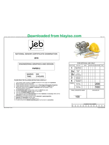
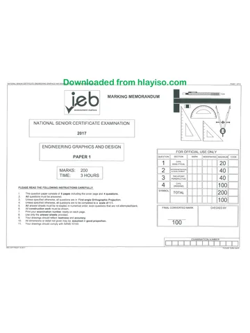
NATIONAL SENIOR CERTIFICATE: ENGINEERING GRAPHICS AND DESIGN: PAPER 2
PAGE 1 OF7
assessment matters
- NATIONAL SENIOR CERTIFICATE EXAMINATION
oO
‘4
oO 2017
2
=_
[ FOR OFFICIAL USE ONLY
ENGINEERING GRAPHICS AND DESIGN [question I SECTION l MARK [MoveRaTeD|[ Maximum CODE
MECHANICAL
PAPER 2 1 ANALYTICAL 20
Locus
: LOCUS
MARKS: 200 2.2 vesinsw 15
TIME: 3 HOURS 2 | somernc 40
DRAWING
PLEASE READ THE FOLLOWING INSTRUCTIONS CAREFULLY 4 MECHANICAL 1 00
ASSEMBLY
1. This question paper consists of 7 pages including the cover page and 4 questions. L
2. All the questions must be answered. SYMBO TOTAL 2 00
3. Unless specified otherwise, all questions are in Third Angle Orthographic Projection.
4. Unless specified otherwise, all questions are to be completed to a scale of 1:1. TOTAL 1 00
5. All answer sheets must be stapled in numerical order and handed in, even
unattempted/blank questions.
6. All construction work must be shown, even if a stencil was used. FINAL CONVERTED MARK CHECKED BY
7. Print your examination number neatly on each page.
8. Use only the answer sheets provided.
9. Your drawings should be well presented and reflect neatness and accuracy, Marks will be
deducted for untidy and inaccurate work. pce
10. Any dimensions or detail not given may be assumed in good proportion. i @) @)
11. Stencils and calculators may be used.
12. All drawings must adhere to the SANS 10111-1.
13. In order to save time, detailed assembly parts must be drawn to convention.
EXAMINATION NUMBER
[EB COPYRIGHT © 2017 PLEASE TURN OVER
You're offline
Skip to contentQuestion paper View all
EGD P2 2017 hlayiso.com
Electronic Graphics and Design · Grade 12 · 2017. Question paper, 7 pages. Read online or download the PDF.
- Subject
- Electronic Graphics and Design
- Grade
- Grade 12
- Document type
- Question paper
- Year
- 2017
- Paper
- 2
- Publisher
- IEB
- Pages
- 7
- File size
- 1.9 MB
Loading document…
Loading document…
1 of 7
Document textSearch extracted text and jump to a page.
NATIONAL SENIOR CERTIFICATE: ENGINEERING GRAPHICS AND DESIGN: PAPER 2 : PAGE 2 OF7
1.12 Calculate the
meter 11 in Figure F.
pl)
Figure A Figure B MECHANICAT
ANALYTICAL
Answer the following questions neatly and legibly in the space provided: |
Q y 1.1 Name the type of hole shown at 1 in Figure A. (1)
t 1.2 Name the type of hole shown at 2 in Figure A. a)
ZY yy t i -—+ {-——=-=} @ 1.3 What type of sectioning is shown in Figure B? ay
t 7 eee 4.4 Calculate the radius 3 in Figure C. (ty
— 1.5 Whatis feature 4 in Figure C called? (1)
4.6 Which screw in Figure D would fit completely into
£ hole 5 and produce a near flush top surface? a
(eo) . 1.7 Which screw in Figure D would fit completely into
(o) Figure C Figure D hole 6 and produce a near flush top surface? (1)
- 1.8 Whatis feature 7 in Figure E called? a)
oO} 1.9 Whatis feature 8 in Figure E called? a)
Q 1.10 Calculate the dimension 9 in Figure E. (1)
&
wT O w wT ow 4.41. Calculate the diameter 10 of the ball in Figure F. oy
A 8 c D E
1.13 What is the thickness of the thread in Figure G? (1)
g 8 1.14 Is the thread in Figure G external or internal? (1)
A a | 1.45 Calculate the diameter 12 of the circle in Figure H. (1)
2 HOLES 12 a 1.16 Caloulate the diameter 13 of the circle in Figure H. (ty
4.17 The machining symbol in Figure | shows the following information: (2)
Select and circle the correct option.
‘ Option | Machine allowance | Roughness value | Direciion offay ] Finvsh
Figure F x o2 08 Cireuar Prating
5 05 02 =
c 02 os Parallel Praling
i D = a2 Perpendicular | Plating
aj err 1.18 The welding symbol in Figure J shows the following information: (2)
Select and circle the correct option.
Figu reE —h. el ath ‘Option Weid yoo Site weld Weld all around | Process
7 A Bead No Yes Fiame
8.8, 1410 FO sa: = it Yer We ie
Q [| —S----}E € Bevel No No Flame
ON PCD 24 D it Yes Yes Are
: Figure | Figure J
ee tai H PLATING
Co Figure G 08
7 0. =
M6x1 2
20 MARKS
EXAMINATION NUMBER
ANSWER SHEET 1 | | |
IEB COPYRIGHT ©2017 PLEASE TURN OVER
NATIONAL SENIOR CERTIFICATE: ENGINEERING GRAPHICS AND DESIGN: PAPER 2
PAGE 3 OF 7
Downloaded from hlayiso.com
30° 90°
or 60°
150°
120°
210°
180°
240°
270°
300°
ANSWER SHEET 2.1
330°
360°
Given is the incomplete graph of displacement
of a wedge-ended follower as well as the centre
of the camshaft as shown by the given centre lines.
The graph of displacement has the following motion:
¥ 0°—120° the follower rises 40 mm with
simple harmonic motion. (Given)
¥ 120°—150° the follower is at rest,
(Uniform motion)
¥ 150°—180°* the follower rises 20 mm.
(Uniform motion)
¥ 180°—360° the follower returns to its
original position with uniform
acceleration and retardation.
The cam profile has the following specifications:
> The direction of turn is anti-clockwise,
> The camshaft has a radius of 9 mm.
2.1.1 Draw the complete graph of displacement.
2.1.2 Draw the cam profile.
2.1.3 Draw the camshaft with hatching.
2.1.4 Draw the wedge-ended follower (to your own
appropriate size and measurements).
2.1.5 Draw the direction of rotation.
2.1.6 Print, in capitals, the required /abef at A and the
>
\SSESSMENT CRITERIA
Graph 12/2
Setup/Plot Points 1
Locus
Shafi and hatch
Follower
Direction
Label/Scale
SSs8sssss
Naaandoa
EXAMINATION NUMBER
| | | | J
IEB COPYRIGHT © 2077
PLEASE TURN OVER
NATIONAL SENIOR CERTIFICATE: ENGINEERING GRAPHICS AND DESIGN: PAPER 2
PAGE 4 OF7
Downloaded from hlayiso.com
ANSWER SHEET 2.2
(QUESTION 2.2]
LOCUS
MECHANISM
‘The given figure shows @ wheel, rotating around
the centre O, with a rod AD attached to it at point A.
Rod BC is pin-jointed at point B and free to move
about its anchor point C. Rods AD and DP are fixed
at 90°. Rod BC rocks back and forth as the wheel rotates,
Construct and draw the locus of point P if the
direction of rotation is clockwise.
Show all constructions and indicate the direction
correctly,
ASSESSMENTCRITERIA] [SET |
@ Setup 2
Plot Points 141
@ Direction 1
@__Locus 1
15 MARKS
EXAMINATION NUMBER
1 i tt] TT 4)
IEB COPYRIGHT © 2017
PLEASE TURN OVER
Downloaded from hlayiso.com
NATIONAL SENIOR CERTIFICATE: ENGINEERING GRAPHICS AND DESIGN: PAPER 2 PAGE 5 OF 7
a
CONSTRUCTION AREA QUESTION 3
ISOMETRIC:
| "oRAWNS |
The figure below shows the top view, front view and
left view of a heavy duty CASTING. The CASTING
has been cut by a cutting plane A-A.
3.1 Draw a neat Sectioned Isometric on the
cutting plane A-A.
3.2 Show the construction for the hexagon.
3,3 Draw the centre lines for the circle.
3.4 Make point P the lowest part of your drawing.
3.5 Start your drawing on the given crosshairs.
ASSESSMENT CRITERIA
Construction ES
a 22
a 4
@ 3
@ Hatching 5
@ ~Non-hatching 2
@ Positioning 2
40 MARKS
EXAMINATION NUMBER
ANSWER SHEET 3
IEB COPYRIGHT © 2017 PLEASE TURN OVER
NATIONAL SENIOR CERTIFICATE: ENGINEERING GRAPHICS AND DESIGN: PAPER 2
PAGE 6 OF 7
PART A
PART G
uf
+!
M6x1
-
r
PART B
160
PART H
r+ 20
4100
30
F
2
SSS SS a
2 HOLES @12
100
|
30
fe
414
R10
PART C
OL,
PART D
Downloaded from hlayiso.com
M6x1
R13 AS
S84
10 BALLS @7
ON PCD 21
QUESTION 4
MECHANICAL
ASSEMBLY
Figure 2 shows a series of pictures of a sliding
GATE WHEEL assembly, as well as an
exploded view of how the components of a si
simplified system are assembled. A list of
components is also shown.
lar,
Figure 1 shows the different components (not
drawn to scale) that need to be assembled.
Complete the following on answer sheet 4
toa SCALE of 1:1
44 A ull sectional Front View of the assembled
components on the cutting plane A-A.
4.2 A Right View of the assembled
components on the given centre lines.
4.3 Please note the following:
Show 3 faces for the hexagonal nut
‘on the front view.
4.4 Show hidden detail on the right view of
only the Gate Frame (Part A) without the holes
for the screws, and on only ONE of the two
Wheels (Part G),
4.5 Draw the cutting plane and the centre lines.
4.6 Draw 3 functional dimensions.
4,7 Draw the projection symbol in the space provided,
4.8 Print the title and scale in the space provided.
4.9 Label the sectioned view.
FRONT VIEW
PARTA
L COMPONENT LIST |
NO. PART | QUANTITY || MATERIAL |
A |GATEFRAME| 7
MILD STEEL]
R2
c
D [M12 BOLT 2 [MILD STEEL]
ol Lt
PARTE
IL
2
2
WHEEL | 2 [MILD STEEL
[8 [eRADLE | 1
|
|
|
H [BEARING [| 4 [steer |
=
a
a PARTE PARTE
18
PARTH
sal
PART H
PART G
EXAMINATION NUMBER
fear] |]
| i J i TTT)
IEB COPYRIGHT © 2017
PLEASE TURN OVER
NATIONAL SENIOR CERTIFICATE: ENGINEERING GRAPHICS AND DESIGN: PAPER 2 PAGE 7 OF 7
QUESTION 4
MECHANICAL
ASSEMBLY,
ASSESSMENT CRITERIA|
FRONT VIEW
|GATE FRAME,
ICRADLE jp
16 SCREW
M12 BOLT
ASHER
[M12 NUT
WHEEL ayo)
BEARINGS
TOTAL] 44
ZIO|AM/G\o|ay>
4
6
4
120 6
2
5
9
8
RIGHT VIEW
AGATE FRAME [5
BICRADLE iol 5
E |wasHeR 2
| DiFMi2 NUTIBOLT | 8
2
6
G/WHEEL
HIDDEN DETAIL
' TOTAL| 28
= - = ADDITION.
CORRECTASS. 5)
; HATCHING 4,
NON-HATCHING
A
4
7
3
CENTRE LINES 3
3
2
Z
2.
2
DIMENSIONS
ra) ! CUTTING PLANE
SYMBOL
ia) TITLE/SCALE
LABEL
TOTAL | 28
[TOTAL | 100
TITLE
SCALE SYMBOL
EXAMINATION NUMBER
[answersneera) froomarg {|_| | LLL]
IEB COPYRIGHT © 2017
Recommended for this subject
Published documents with matching subject and grade metadata.
Related documents
Matched using subject, grade, language, document type and exam metadata.
More from Grade 12 Electronic Graphics and Design
Explore more published documents in this catalogue.