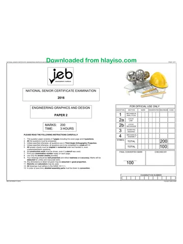
°
pa nenm—cnnae i natnlndisd from Mayisa.com
WY wes ment matters
MARKING GUIDELINES
2019
NATIONAL SENIOR CERTIFICATE EXAMINATION
ENGINEERING GRAPHICS AND DESIGN
PAGE 1 OF 6
FOR OFFICIAL USE ONLY |
PAPER 1 jquestion|/ section || maRK | MopeRaTED|[Maximuw|| cove |
CIVIL
1 ANALYTICAL 2 0
MARKS: 200 2 |imemery 40
TIME: 3 HOURS 3 TWO-POINT 40
PERSPECTIVE
civIL
DI
PLEASE READ THE FOLLOWING INSTRUCTIONS CAREFULLY 4 earns 1 00
1. This question paper consists of 6 pages including the cover page and 4 questions. TOTAL 200
2. All questions must be answered.
3. Unless specified otherwise, all questions are in First-angle Orthographic Projection. CHECKED BY
4. Unless specified otherwise, all questions are to be completed toa scale of 1:1.
5. All answer sheets must be restapled in numerical order, even questions that have not been answered.
6. All construction work must be shown.
7. Print your examination number neatly on each page.
8. Use only the answer sheets provided.
9. Your drawings should reflect neatness and accuracy.
10. All dimensions or detail not given may be assumed in good proportion.
11. Your drawings should comply with SANS 10143.
EXAMINATION NUMBER
PLEASE TURN OVER
IEB COPYRIGHT © 2019
You're offline
Skip to contentQuestion paper View all
EGD P1 2019 hlayiso.com
Electronic Graphics and Design · Grade 12 · 2019. Question paper, 5 pages. Read online or download the PDF.
- Subject
- Electronic Graphics and Design
- Grade
- Grade 12
- Document type
- Question paper
- Year
- 2019
- Paper
- 1
- Publisher
- IEB
- Pages
- 5
- File size
- 2.1 MB
Loading document…
Loading document…
1 of 5
Document textSearch extracted text and jump to a page.
NATIONAL SENIOR CERTIFICATE: ENGINEERING GRAPHICS AND
ERF 4199
PROPOSED
NEW
/ UNIT
Zia
=
IPROPOSED|
NEW
UNIT
EXISTING
RETIREMENT
HOME
\
ERF 5199 \O
\ //
d from hlayiso.com
NATURE
RESERVE
ERF 4201
/|
|
/ PROPOsED| _| PROPOSED
NEW NEW
UNIT UNIT /
© ERF 4200 : C) yf
BAL 5000 _ . _ . L . /
105
ERF 5200
ERF 5201
SCALE 1:500
PAGE 20F 6
QUESTION 1
CIVIL
STUDY THE ADJACENT DRAWING AND ANSWER THE QUESTIONS THAT FOLLOW:
1.1 What type of civil drawing is shown? SITE PLAN
1,2 Which ERF is to the NORTHEAST of the retirement complex? ‘5199
1.3 How many manholes are there in this drawing? 4
1.4 Which corer has the lowest elevation? {either A,B,C,D,E or F) Cc
1.5 How many trees need to be removed? 5
1.6 What is the feature at 1 called? CORNER / BEACON HEIGHT]
1.7 What is the feature at 2 called? BUILDING LINE
1.8 What is the feature at 3 called? WATER TANK
1.9 What is the feature at 4 called? SEWER LINE
1.10 What is indicated at feature 5? WORK TO BE REMOVED:
1.11 Has the ramp been drawn correctly? NEE
1.12 What is the feature at 6 called? CONTOUR
1.13 What is the feature at 7 called? FIRE HYDRANT
1.14 What is the feature at 8 called? SEPTIC TANK
1.15 In what colour would a proposed new unit be drawn on this plan? RED/GREY
1.16 Is this drawing drawn to the scale indicated? NO
1.17 What does the abbreviation IE stand for? INSPECTION EYE
1.18 What is the closest that a new unit can be placed to ERF 5200? 5000 mm/5m
1.19 In the space below, determine the area of the Frail Care Centre in m*
Area = length x breadth
Answer: 400 m?
EXAMINATION NUMBER
ANSWER SHEET 1
IEB COPYRIGHT © 2018
PLEASE TURN OVER
Ww
PAGE 30F 6
mot secon ccemeon OWMOaded from hlayiso.com
20 =460x Pi
INTERPENETRATIO!
& DEVELOPMEN
The drawings below show the COMPLETE Top and Right
View as well as the INCOMPLETE Front View of a
CYLINDRICAL PIPE which has been joined together with
a SQUARE DUCT and drawn in First-angle Orthographic
Projection. An Auxiliary View of the square duct is also
shown in the Top and Front Views.
Draw the following:
2.1 the complete Front View clearly showing the curve
of interpenetration. Show all hidden detail.
2.2 the development of only half of the cylindrical pipe
which joins with the duct, clearly showing the curve of
interpenetration.
Show all construction and calculations,
Do not draw the right view.
The complete Top View and an Auxiliary View have
already been drawn in position.
ASSESSMENT CRITERIA
‘You will be assessed on your ability to do the following:
«draw and complete the Front View 24)
* show necessary construction 2
* — develop and draw the cylindrical pipe 14,
2 | 8
‘ %
£
Gwen @
Front View.
Hidden Detail = B60,
Interpen .
‘Square outer lines @ = 3
Construct =2
Calculation =2
Development =12
120}
EXAMINATION NUMBER
ANSWER SHEET 2
IEB COPYRIGHT © 2019
PLEASE TURN OVER
.
The figures show the three views of the inside of a
tuck shop with built-in cupboards and a semi-circular
serving hatch. Some walls have been removed to see
inside the room,
Draw a neat two-point perspective view of the tuck
shop.
PTS + 60/2= 30 PP - Picture Plane
HL - Horizon Line
GL - Ground Line
CON © = 2 SP - Station Point
Ars @ = 7 Neatly label the vanishing points RVP and LVP.
VPS + 214 NO HIDDEN DETAIL IS REQUIRED.
Fol ASSESSMENT CRITERIA
° You will be assessed on your ability to do the following:
* determine and label the vanishing points 1
© draw the two-point perspective view 39
PP_HL | HL PP
P|
RVP
fed
T
|
i]
! |
Fo '
|
a
GL
EXAMINATION NUMBER
ANSWER SHEET 3
IEB COPYRIGHT © 2019 PLEASE TURN OVER
vow necro DOWNOAded from hlayiso.com secre
QUESTION 4,
CIVIL
DRAWING
Assessment Criteria
" Sectional Elevation
Ceiling Battens
|Wall Plates
Ceiling Board
Truss Plates
Roof Truss
Purlins
Roof
‘Sectioned Walls
‘Sectioned Window
|0|Floor & Foundation
11|/DPC.
12| Hatching
}3{Internal Door
14\Basin
S|External Walls
16|Fascia Boards
rad 17|Roof Detail
j2 200 at 18|Finished Floor Level
VILLLLLLLA 19)Labels
yy 23 23 eee - Y
j 2 BIC 24 Y Subtotal
Floor Plan
\20\ Walls
21|Hatching
\22| Window
23, Doors
'24\Cupboard
’5|Plumbing Fixtures
26\Labels
27|Ramp
28) Cutting Plane
TOTAL | | |
WEN
olol/slolalalo[n[=
a
# FFL
% NGL”
2
a
20
wD
SCALE 1:50 76
FLOORPLAN 76
EXAMINATION NUMBER
ANSWER SHEET 4
IEB COPYRIGHT © 2019
Recommended for this subject
Published documents with matching subject and grade metadata.
Related documents
Matched using subject, grade, language, document type and exam metadata.
More from Grade 12 Electronic Graphics and Design
Explore more published documents in this catalogue.