
Downloaded from hlayiso.com
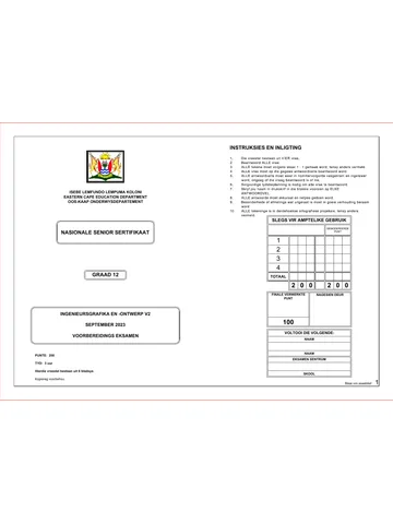
INSTRUCTIONS AND INFORMATION
ISEBE LEMFUNDO LEMPUMA KOLONI
EASTERN CAPE EDUCATION DEPARTMENT
OOS-KAAP ONDERWYSDEPARTEMENT
FOR OFFICIAL USE ONLY
MODERATED
NATIONAL MARK
SENIOR CERTIFICATE 1
2
3
4
TOTAL
GRADE 12
2 0 0 2 0 0
FINAL CONVERTED CHECKED BY
MARK
*GRDSE1*
ENGINEERING GRAPHICS AND DESIGN P1
100
SEPTEMBER 2018
COMPLETE THE FOLLOWING:
PREPARATORY EXAMINATION
NAME
NAME
MARKS: 200
EXAMINATION CENTRE
TIME: 3 hours
This question paper consists of 6 pages.
EXAMINATION CENTRE
Copyright reserved Please turn over 1
Skip to contentAll 2018 papers 
View all
Engineering Graphics and Design Grade 12 P1 2018 QP (Eng)
Grade 12 Engineering Graphics and Design Paper 1 question paper from the Eastern Cape Mock Exam 2018 (English), 6 pages. Read online or download the free PDF.
Engineering Graphic And Design · Grade 12 · Eastern Cape Mock Exam · 2018. Question paper, 6 pages. Read online or download the PDF.
- Subject
- Engineering Graphics and Design
- Grade
- Grade 12
- Document type
- Question paper
- Year
- 2018
- Exam period
- Eastern Cape Mock Exam
- Paper
- 1
- Curriculum
- CAPS
- Pages
- 6
- File size
- 763.1 KB
Free to read online, no sign-up needed
Loading document…
Loading document…
1 of 6
This exam
Questions in this paper
Document textSearch extracted text and jump to a page.
Engineering graphichs and design / P1 Downloaded from hlayiso.com
LAND SURVEYOR'S CERTIFICATE NOTE:
NCS
QUESTION 1: ANALYTICAL (CIVIL)
EC / September 2018
AP
LE
OF THE SIDE LENGTHS AND Contractors must verify all dimensions and
ST
CORNER HEIGHTS ON STAND 102. levels on site before commencing work. Given:
Architects to be notified immediately of any
SURVEYED ON 2018-07-20 discrepancies. The site plan for an existing house with new proposed buildings, a title panel and a table of questions. The drawing
LENGTHS IN CORNER HEIGHTS IN has not been prepared to the indicated scale.
MILLIMETERS METERS ARCHITECT'S SIGNATURE ...........................
AB = 45800 A = 820 Instructions:
BC = 84000 B = 808 CLIENT'S SIGNATURE ................................... Complete the table below by neatly answering the questions, which refer to the accompanying drawing and title
CD = 46000 C = 807.7 panel. [25]
DA = 87000 D = 821
QUESTIONS ANSWERS
1 What is the reference code of the drawing? 1
ANSWER 17
2,1 m FENCE : FACEBRICK PILLARS
A DU PLESSIS STREET
WITH PALISADE
In the space provided below, draw, in
2 Who checked the drawing? 1
neat freehand, the front view and top
MH view of the SANS 10143 convention
B for a single URINAL. 3 On what date was the site plan printed? 1
ELECTRICAL SLIDING GATES
BL 4000 W
4 What revision must be done to the site plan? 1
2200 5
ORANGE ORCHARD Who is the owner of stand 102? 1
6 What feature is visible to the west of stand 102? 2
What is the height of the fence around the tennis court in
7 1
mm.
8 What does the abbreviation RE stand for? 1
FALL OF TAR SURFACE
SEWERAGE 9 What does the abbreviation W stand for? 1
LINE 1 : 10
STAND 102 How many inspection eyes are required for the new
10 1
buildings?
RE NEW PAVING
IE
11 What feature is indicated by arrow A? 1
RAILWAY LINE
NATURE RESERVE
EXITING HOUSE
12 What feature is indicated by arrow B? 1
IE
What colour is used to indicate new buildings on a site
NEW 13 1
IE RE
plan?
GARAGE
What colour is used to indicate an existing sewerage on
14 1
a site plan?
BL 2000
NEW BRAAI AREA
BL 2000
IE 12600 15 In the space provided below, determine the perimeter of the stand 102 in meters. 2
6200 9500
RE
SWIMMING POOL
INDICATE THE TYPE In the space provided below, determine the total area of the PAVING around the swimming
16 4
A 2017-08-12 OF FENCING USED pool in square meters.
15200 FENCE: DIAMOND
WIRE 2,4m HIGH In the space provided in the title panel, draw, in neat freehand, the front view and top view
REVISION DATE DESCRIPTION 17 4
of the SABS 10143 convention for a SINGLE URINAL.
PRINTED BY DATE OF PRINT
TENNIS COURT OFFICE FOR YOU 2018-09-01 TOTAL 25
ACRYLIC SURFACE DRAWING TITLE
ANSWER 15 ANSWER 16
SITE PLAN
Show ALL calculations Show ALL calculations
PROJECT
B PROPOSED NEW OUTBUILDINGS
TAR SURFACE
AND PAVING FOR MR. M. MULLER
BL 2000 ON STAND 102, 3 DU PLESSIS
C STREET, PATENSIE
PROJECT NUMBER DRAWING NUMBER
D 2,1 m ELECTRICAL FENCE 09-2018 01012018
DATE DRAWN CHECKED SCALE
MAIN ROAD NAME
2018-01-21 KYLE REBECCA 1 : 300
REFERENCE CODE
SITE-2018 NAME 2
Copyright reserved Please turn over
Engineering graphichs and design / P1
Downloaded from hlayiso.com
NCS EC / September 2018
QUESTION 2: INTERPENETRATION AND DEVELOPMENT
LE
AP
ST
Given:
x The incomplete front view and complete top view of two
square pipes penetrating one another.
x Starting point X for the top view.
x Starting points AB for the development of the branch
pipe.
Instructions:
Draw to scale 1 : 1, the following views of the interpenetrating
pipes:
2.1 The top view. (start at point X)
2.2 The complete front view, clearly showing the curve of
interpenetration.
2.3 The surface development of the branch pipe with AB as
the seam.
x Show ALL hidden detail and folding lines.
x Show ALL necessary construction lines.
[32]
30
8
80
0°
12
45
X
X
A B
SEAM
ASSESSMENT CRITERIA
TOP VIEW & CENTRE
1 LINES 7
2 FRONT VIEW 12
A
3 CONSTRUCTIONS 2
4 DEVELOPMENT 11
PENALTIES (-)
TOTAL 32
B
NAME
NAME 3
Copyright reserved Please turn over
Engineering graphichs and design / P1 Downloaded from hlayiso.com
NCS
QUESTION 3: PERSPECTIVE
EC / September 2018
LE
AP
ST Given:
x Two views of a BRAAI AREA and the information
needed to draw a two-point perspective drawing
x A Side view of wall A
SE R
AT PP − Picture plane
37
AT
SE HL − Horizon line
GL − Ground line
WA Side view of wall A as seen in
SP − Station point
LL
A the direction of the arrow B. Instructions:
B Complete the perspective drawing.
x Align the drawing sheet with the ground line (GL).
x Determine and label the vanishing points.
x Show ALL necessary construction.
x NO hidden detail is required. [45]
ASSESSMENT CRITERIA
PP 1 CONSTRUCTION + VPs 4
2 BRAAI & SEAT 23
3 WALLS & ROOF SLAB 13
4 CIRCLE 5
TOTAL 45
WALL A
HL
SEAT
GL
NAME
SP NAME 4
Copyright reserved Please turn over
Engineering graphichs and design / P1
Downloaded from hlayiso.com NCS EC / September 2018
QUESTION 4: CIVIL DRAWING
LE
AP
ST 250 x 20 mm BARDGE BOARD FLOOR FINISHES Given:
DOOR AND WINDOW SCHEDULE
250 x 20 mm FACIA BOARD x The incomplete north elevation of a house, showing the walls,
120° IBR SHEET: 50mm OVERHANG 1 BEDROOM: CARPET the windows, the door opening, the roof and notes.
TO FIT 1000
100 x 150 mm GUTTER 2 BATHROOM: TILE
400 x The incomplete floor plan showing the roof line, walls, position
WINDOW OPENING 3 KITCHEN: TILE of the doors, windows, fixtures and electrical layout.
4 LIVING AREA: LAMINATED
DOOR OPENING
x A schematic diagram of a roof truss and roof notes
2750 FLOORING A
2500 Ø80 RAIN WATER DOWNPIPE
B
800 x The incomplete foundation and wall detail
FINISHED FLOOR LEVEL A
x Room designations and floor finish
2 x A door and window schedule
2050
GROUND LINE 3
GULLEY 350 x 350 x 150mm WINDOW (W1) x A table of sanitary fixtures
HEIGHT OF
INCOMPLETE NORTH ELEVATION 2 STEPS: HEIGHT 200mm PER x A table of roof components
WALL 2050mm STEP 1500 x A table of electrical symbols
1 4
650
W1 W1 FEATURES x A table of rainwater items
D1 D1 DOOR x The floor plan of the house, drawn to scale 1 : 50 and the
WC 6 S W1 WINDOW
SH DOOR FRAME AND A incomplete foundation of the detailed section, drawn to
W2 WINDOW DOOR (D1) scale 1 : 20 on page 6.
ROOM DESIGNATIONS 1500
4 3 B
FIXTURES
WB D1 4 WC TOILET A Instructions:
WINDOW NOTES
1 COUNTER TOP WB WASH BASIN
A = OPENING SIDE B Answer this question on page 6.
D1 SH SHOWER
1 2 B = FIXED PANE 4.1 Using the given incomplete floor plan, draw, in first-angle
S SINK
FRAME 50 mm
WINDOW (W2) orthographic projection and to scale 1 : 50, the following
ELECTRICAL FITTINGS views of the house:
6 1. LIGHT SWITCH - SINGLE-POLE SILL: 200 x 30 mm FIBRE CEMENT SILL UNDER 4.1.1 THE COMPLETE FLOOR PLAN
4 4 140
2. LIGHT SWITCH - DOUBLE-POLE ALL WINDOWS
Add the following features to the drawing:
3. FLUORESCENT LIGHT 2 x 40 W
4. CEILING LIGHT x ALL doors and windows
2 6 5. WALL MOUNTED LIGHT x ALL fixtures as indicated by abbreviations
W2
D1
W2 6. SWITCHED SOCKET OUTLET
RAINWATER ROOF COMPONENTS x ALL electrical fittings as indicated by numbers
ITEMS x ALL hatching detail
250 x 20 mm FASCIA BOARD
ROOF LINE: NOTE:
5 4.1.2 THE NORTH ELEVATION
END OF FACIA THE ARROWS ON THE FLOOR 300
PLAN SHOW THE LIGHT ROOF CAP Show the following features on the drawing:
INCOMPLETE FLOOR PLAN 100 150
100
CONNECTION TO THE SWITCH. x The outside walls, steps, window and door detail
75 x 50 mm PURLINS x The roof detail, including the fascia board, gutter, rain-
30°
ROOF NOTES: 25 mm water down pipes, gulley, barge board and roof ridge
SCREED x The finished floor level
ROOF PITCH 30° WITH 250 x 20 mm FACIA BOARD ON THE
ELECTRICAL SYMBOLS
240
SIDES 4.2 In the space provide on page 6, draw, to scale 1 : 20, a
ROOF CAP MUST BE FITTED ON THE RIDGE.
GROUND LEVEL 550 DETAILED SECTION on cutting plane A-A of the area in the
Ø 80
ellipse shown on the floor plan.
250 x 20 mm BARGE BOARDS ON THE ROOF ENDS 200 x Show the following features on the drawing:
RWDP
400 x The complete foundation, external wall with window detail
ROOF COVER 50 mm IBR SHEET ON 75 x 50 mm PURLINS 150 GL
@ 1000 mm c/c
INCOMPLETE NON LOAD and shower wall.
W
2 X 110 x 100 BEARING WALL AND n x 40 W
x The roof detail, including the fascia board and gutter.
mm LINTEL FOUNDATION DETAILS 350
114 x 38 mm ROOF TRUSS ON 114 x 38 mm WALL PLATES x ALL hatching detail. ONLY the substructure hatching
ABOVE DOOR 2460 GULLEY 150 may be drawn in neat freehand.
9 mm CEILING BOARD ON 38 x 38 mm BRANDERING AND WINDOW
STRIPS @ 400 mm c/c OPENINGS x The completed break line.
SANITARY FIXTURES x Start at the given starting point.
100 x 150 mm GUTTER ON ALL THE SIDES
25 mm 500
SCREED
400 Label the following:
100
x The north elevation and scale.
400
2050 x The room designations and floor finishes.
200
850 750 850
550 GROUND LEVEL 100 x Using the correct abbreviations, label the following features in
250 400 the correct view: ground level; finished floor level and damp
FLOOR LEVEL
200 proof course.
600
/c
0 0c INCOMPLETE LOAD BEARING 400 600
200
900
500 350 NOTE:
10 WALL AND FOUNDATION
ALL drawings must comply with the guidelines and graphical
c/c DETAIL 1200
00 900 symbols contained in the SANS 10143. [98]
10 WASH BASIN TOILET SINK (S)
SHOWER
EQUAL EQUAL EQUAL EQUAL (WB) (WC)
(SH)
SCHEMATIC DIAGRAM OF THE ROOF
5
Copyright reserved Please turn over
Engineering graphichs and design / P1 Downloaded from hlayiso.com
NCS EC / September 2018
LE
PENALTIES
AP
ST
1 INCORRECT OVERALL SCALE
2 INCORRECT POSITIONING OF VIEWS
3 NON-ALIGNMENT OF VIEWS
TOTAL PENALTIES (-)
ASSESSMENT CRITERIA
FLOOR PLAN
1 DOORS + WINDOWS 11 21
2 ELECTRICAL 10
3 FIXTURES 6
4 HATCHING 3
5 LABELS 4
SUBTOTAL 34 21
A NORTH ELEVATION
1 ROOF, GUTTER,
FACIA, BADGE BOARD 11
2 WALLS + STEPS +
GULLEY 7
3 DOORS + WINDOWS 11 21
A
4 LABELS 2
SUBTOTAL
COUNTER TOP 31 21
DETAILED SECTION
1 ROOF DETAIL 10
2 FOUNDATIONS +
WALLS + SLAB 9
3 SILL + WINDOW +
SHOWER + LINTELS 4
4 HATCHING 7
5 LABELS 2
SUBTOTAL 32
TOTAL 98
PENALTIES (-)
STARTING POINT FOR FINAL TOTAL
INCOMPLETE BREAK LINE DETAILED SECTION
FOR DETAILED SECTION
FLOOR PLAN NAME
DETAILED SECTION ON A-A SCALE 1 : 50
SCALE 1 : 20 STEP
NAME 6
Copyright reserved
Study this subject
Recommended for this subject
Memorandum
Engineering Graphics and Design Grade 12 P1 2018 Memo
Question paper
Engineering Graphics and Design Grade 12 P2 2018 QP (Eng)
Question paper
Engineering Graphics and Design Grade 12 P1 NSC June 2018 QP
Question paper
Engineering Graphics and Design Grade 12 P1 2018 QP (Afr)
Question paper
Engineering Graphics and Design Grade 12 P1 2013 QP
Memorandum
Engineering Graphics and Design Grade 12 P1 2025 Memo
More from Grade 12 Engineering Graphics and Design
Memorandum
Engineering Graphics and Design Grade 12 P2 2025 Memo (Eng)
Memorandum
Engineering Graphics and Design Grade 12 P2 2025 Memo
Memorandum
Engineering Graphics and Design Grade 12 P2 2024 Memo (Eng)
Memorandum
Engineering Graphics and Design Grade 12 P1 2023 Memo (Afr)
Question paper
Engineering Graphics and Design Grade 12 P2 2023 QP
Question paper