
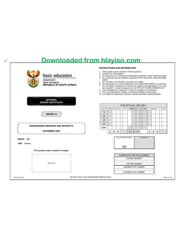
basic education
Department
« y) Basic Education
"4 REPUBLIC OF SOUTH AFRICA
NATIONAL
SENIOR CERTIFICATE
if ENGINEERING GRAPHICS AND DESIGN P2 \
it NOVEMBER 2015 }
MARKS: 100
TIME: 3 hours
This question paper consists of 6 pages.
INSTRUCTIONS AND INFORMATION
This question paper consists of FOUR questions.
Answer ALL the questions.
ALL drawings are in third-angle orthographic projection, unless otherwise stated.
ALL drawings must be completed using instruments, unless otherwise stated.
ALL answers must be drawn accurately and neatly.
ALL the questions must be answered on the QUESTION PAPER as instructed.
ALL the pages, irrespective of whether the question was attempted or not, must
be re-stapled in numerical sequence in the TOP LEFT-HAND CORNER ONLY.
8. Time management is essential in order to complete all the questions.
9. Print your examination number in the block provided on every page.
10. Any details or dimensions not given must be assumed in good proportion.
NOARON>
FOR OFFICIAL USE ONLY
QUESTION |] MARKS OBTAINED | } | SIGN MODERATED 3] SIGN RE-MARKING 3] SIGN
1
2
3
4
TOTAL
2/;0/0 2/;0/0 2/0/0
FINAL CONVERTED MARK CHECKED BY
100
COMPLETE THE FOLLOWING:
CENTRE NUMBER
CENTRE NUMBER
EXAMINATION NUMBER
EXAMINATION NUMBER
Copyright reserved
Please tum over
Skip to contentAll 2015 papers 
View all





Engineering Graphics and Design Grade 12 P2 2015 QP (Eng)
Grade 12 Engineering Graphics and Design Paper 2 question paper from the NSC November Exam 2015 (English), 6 pages. Read online or download the free PDF.
Engineering Graphic And Design · Grade 12 · NSC November Exam · 2015. Question paper, 6 pages. Read online or download the PDF.
- Subject
- Engineering Graphics and Design
- Grade
- Grade 12
- Document type
- Question paper
- Year
- 2015
- Exam period
- NSC November Exam
- Paper
- 2
- Curriculum
- CAPS
- Pages
- 6
- File size
- 1.8 MB
Free to read online, no sign-up needed
Loading document…
Loading document…
1 of 6
This exam
NSC November Exam 2015
Questions in this paper
Document textSearch extracted text and jump to a page.
Engineering Graphics and Design/P2
cg
Downloaded from hlayiso.com
DBE/November 2015
QUESTION 1; ANALYTICAL (MECHANICAL)
Given:
Three views and two detailed enlargements of a tapping valve assembly, a title block and a table of questions.
The drawings have not been prepared to the indicated scale.
{od ' i Instructions:
/ | Complete the table below by neatly answering the questions, which all refer to the accompanying drawings and
| L_ Ly the title block. [30]
4 \ 1 n
—— | ~ 4 | Whatis the title of the assembly? 1
a | Y ‘ 2 | On what date was the drawing drawn? 1
S| oO / \ 3. | What is the drawing number? 1
DETAILS | |
\ Zi) | 4 | What scale is indicated for the drawing? 1
: ia A) 5 | Which drawing program was used? 1
_— | /~ © 6 | Who approved the drawing? 1
oo " 7 | What materlal is used to manufacture the main base? 1
DETAILT
8 | What would VIEW 2 be called? 1
9 |How many socket head bolts are there in the assembly? 1
SAL BL ws 40 | Give the complete dimensions at A B c 3
| jl 11 | Name the feature at F. 1
IT + 8
T 42 | Name the type of section at D. 1
‘ _ > | eas Sort 13 | Why is the component at E filled in solid? 1
on 8 44 | What is the total height of the assembly? 1
ql 05 | | i 15 | What is the purpose of the two enlarged detailed views? 2
if CTI 16 | What is indicated by the convention at G? 1
93 | | With reference to the tolerance, determine the maximum
17 | ee > 2
| ; dimension at H
va) -— pe With reference to the tolerance, determine the minimum
t ,
« LY a 18 | dimension at H? 2
LC f t 19 | Insert the cutting plane on VIEW 3 and label it A-A. 3
2
] a2 5 20 |In the space provided below, draw, in neat freehand, the symbol for the projection system A
— —— used
5 26
RI TOTAL | 30
VIEW 2 VIEW 3
PARTS LIST FILE NAME: RCOMVK 0002.6wg TITLE ‘ANSWER 20
PART QUANTITY MATERIAL, DRAWING No. 2015 - A - 005 TAPPI NG VALVE
1 | VALVE ASSEMBLY 1 REF: DETAILED DRAWING ALL DIMENSIONS ARE IN MILLIMETRES. APPROVED: ANDREW BRAND 2015/01/23
2 SOCKET HEAD BOLT 3 TOOL STEEL DRAWING PROGRAM: AUTOCAD 2015 CHECKED: SOON DENTON 2015/01/16 rs
3 SQUARE BOLT WITH PUNCH 1 TOOL STEEL MATERIALS: STEEL, PEWTER AND RUBBER DRAWN: CHRISTI GREEF 2015/01/05
4 [MAIN BASE 1 PEWTER 15 EDISON BLVD
TAP VALVE TO BE USED FOR
> ler 7 PEWIER ReCO REFRIGERATION meustriat rari | tapping oF 1340, Rt, R22 AND SyMBoL
1914 501 REFRIGERANTS IN COPPER EXAMINATION NUMBER
6 O-RING 1 RUBBER: PIPE ONLY
—— = LULA — a rr
Copyright reserved SE RUM A Please tum over
Engineering Graphics and Design/P2
DBE/November 2015
SCHEMATIC DRAWING
Downloaded from hlayiso.com
QUESTION 2: LOCI
NOTE: Answer QUESTIONS 2.1 and 2.2.
2.1 MECHANISM
Given:
* A schematic drawing of a mechanism consisting
of gear A and gear B as well as a slotted bar CD,
attached at C to gear A
© The position of pin E on gear B
© The position of centre point F
Motion:
As gear A rotates in an anti-clockwise direction, it
drives gear B in a clockwise direction. The slotted
bar CD slides over pin E during the rotation
Instructions:
* Draw, to scale 1:1, the given schematic drawing
of the mechanism.
* Trace the locus generated by point D for ONE
complete revolution of the mechanism.
* Show ALL necessary construction. [19]
FOLLOWER DETAIL
2.2 CAM
Given:
© The detail of a roller-ended follower, drawn to a reduced scale
* The displacement graph and the cam shaft, drawn to scale 1 : 1, in the correct position
Specifications:
* The follower reciprocates along the 30° centre line that runs through the centre of the
cam shaft
* Rotation = clockwise
Instructions:
* Draw, to scale 1: 1, the roller-ended follower in its correct position.
* Project and draw the cam profile from the given displacement graph.
* Show the direction of rotation on the cam profile.
* Show ALL necessary construction. [21]
esgaegeee28 8888
DISPLACEMENT GRAPH
SCALE 6 mm = 30°
Copyright reserved
ASSESSMENT CRITERIA 2.1
1|GIVEN+CENTRELINES | 5
2 | CONSTRUCTION 6
3 | POINTS + CURVE 8
SUBTOTAL 21| 19
ASSESSMENT CRITERIA 22
4 | CONSTRUCTION + 5
FOLLOWER + DIRECTION
2 | PLOTTING 7
3 | CAM PROFILE 6
SUBTOTAL22| 21
PENALTIES (-)
TOTAL} 40
EXAMINATION NUMBER
EXAMINATION NUMBER [3
Please tum over
Engineering Graphics and Design/P2
cg
Downloaded from hlayiso.com
DBE/November 2015
QUESTION 3: ISOMETRIC DRAWING
Given:
©The front view, top view and left view of a
woodworking plane
* The position of point P on the drawing sheet
Instructions:
Using scale 1: 1, convert the orthographic views of
the woodworking plane into a sectional isometric
drawing on cutting plane A-A.
* Make P the lowest point of the drawing
* Show ALL necessary construction.
* NO hidden detail is required. [34]
78 45
30 36
>|
55
fs
Copyright reserved
ey 3 3
LIP
|
ASSESSMENT CRITERIA
1 [cxcne 3
2 | Nonisovetnic 124
3 | HEXAGON 23
4 | CIRCLES + 6
CONSTRUCTION + CL
5 | SECTION 8
6 | HATCHING 2
PENALTIES (-)
ToTAL | 34
EXAMINATION NUMBER
EXAMINATION NUMBER [4
Please tum over
Engineering Graphics and Design/P2
Downloaded from hlayiso.com —
O12
100
28
O12
WORM SCREW [1]
EXPLODED ISOMETRIC DRAWING
lat) Lf ona
M24 f
LEVER [2]
END RING [3]
8 HOLE
=| PLACE(R) HERE —
//-— PLACE (T) HERE
/ PLACE (S) HERE
38
15 |
75.
136
Copyright reserved
PLACEMENT OF
STRONG ARMS
136
M8 BOLT [6]
AF12
QUESTION 4: MECHANICAL ASSEMBLY
Given:
* The exploded isometric drawing of the parts of a bearing
puller assembly, showing the position of each part relative
to all the others
* Orthographic views of each of the parts of the bearing
puller assembly
Instructions:
* Answer this question on page 6
Draw, to scale 1 : 1 and in thirdangle orthographic
projection, the following views of the assembled parts of
the bearing puller assembly:
4.1 Ahalf sectional front view according to cutting
plane A-A. Show the left side in section, as seen from
the direction of the arrow shown on the exploded
isometric drawing. The cutting plane is shown on the
top view of the beam (part 4)
4.2 The top view.
*ALL drawings must comply with the guidelines as
contained in the SANS 10111
NOTE:
© The two strong arms (part 5) must be placed against the
cylindrical part of the beam (part 4) so that points R and T
will be at the indicated positions.
* The worm screw (part 1) must be completely screwed into
the beam (part 4) so that point S will be at the indicated
position.
© The lever (part 2) must be placed in the centre of the worm
screw (part 1),
* Draw only the rear M8 bolt, as indicated by the exploded
isometric drawing
* Show THREE faces of the head of the M8 bolt in the front
view.
* Add the cutting plane A-A to the drawing
* NO hidden detail is required [96]
PARTS LIST
PARTS, QUANTITY MATERIAL,
1 | WORM SCREW 1 HARDENED STEEL
2 | LEVER 1 HARDENED STEEL
3 | END RING 1 MILD STEEL
4 | BEAM 1 HARDENED STEEL
5 | STRONG ARM 2 HARDENED STEEL
6 | Ma BoLt 2 MILD STEEL
8 VON WHEILIG STREET
www.sn_king.co.za
SN KING CC BH ovo 1574
BEARING PULLER
5
Please tum over
a Downloaded from hlayiso.com —
. FOR OFFICIAL USE ONLY
Ce
NOT IN THIRD ANGLE
INCORRECT OVERALL SCALE
INCORRECT HATCHING
PARTS NOT ASSEMBLED
PARTS DRAWN FREEHAND
TOTAL PENALTIES (-)
ASSESSMENT CRITERIA
TOP VIEW
1 | WORM SCREW 3
2 | LEVER 4
3 JENDRING 3
4 | BEAM 43
5 | STRONG ARM 10
6 | Me BOLT 7
SUBTOTAL | 32
SECTIONAL FRONT VIEW
1 | woRM scREW 15
2 | LEVER 7
3 | END RING 3
4 [BEAM 3}
5 | STRONG ARM 103
6 | Mg BOLT 9
SUBTOTAL | 50
GENERAL
1 | CENTRE LINES 3
2 | ASSEMBLY 6
3. | CUTTING PLANE 5
SUBTOTAL | 14
TOTAL| 96
TOTAL PENALTIES(-)
GRAND TOTAL
EXAMINATION NUMBER
HINO A Sauron ——T8
Study this subject
Recommended for this subject
Question paper
Engineering Graphics and Design Grade 12 P1 2015 QP (Afr)
Question paper
Engineering Graphics and Design Grade 12 P1 2015 QP (Eng)
Question paper
Engineering Graphics and Design Grade 12 P2 2015 QP
Question paper
Engineering Graphics and Design Grade 12 P2 2015 QP (Afr)
Question paper
Engineering Graphics and Design Grade 12 P2 2023 QP (Afr)
Question paper
Engineering Graphics and Design Grade 12 P2 2023 QP (Eng)
More from Grade 12 Engineering Graphics and Design
Memorandum
Engineering Graphics and Design Grade 12 P1 2025 Memo
Memorandum
Engineering Graphics and Design Grade 12 P2 2025 Memo (Eng)
Memorandum
Engineering Graphics and Design Grade 12 P2 2025 Memo
Memorandum
Engineering Graphics and Design Grade 12 P2 2024 Memo (Eng)
Memorandum
Engineering Graphics and Design Grade 12 P1 2023 Memo (Afr)
Question paper