
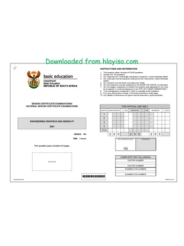
basic education
Department:
« y) Basic Education
REPUBLIC OF SOUTH AFRICA
NATIONAL
SENIOR CERTIFICATE
MARKS: 100
TIME: 3 hours
This question paper consists of 6 pages.
|
|
|
Barcode label |
|
|
|
Copyright reserved
INSTRUCTIONS AND INFORMATION
This question paper consists of FOUR questions.
Answer ALL the questions.
ALL drawings are in first-angle orthographic projection, unless otherwise stated.
ALL drawings must be prepared using pencil and instruments, unless otherwise
stated.
ALL answers must be drawn accurately and neatly.
ALL the questions must be answered on the QUESTION PAPER, as instructed.
ALL the pages, irrespective of whether the question was attempted or not, must
be re-stapled in numerical sequence in the TOP LEFT-HAND CORNER ONLY.
8. Time management is essential in order to complete all the questions.
9. Print your examination number in the block provided on every page.
10. Any details or dimensions not given must be assumed in good proportion.
RONS
NOn
FOR OFFICIAL USE ONLY
QUESTION | MARKS OBTAINED | 3 | SIGN MODERATED +] SIGN RE-MARKING 4 sIGN
1
2
3
4
TOTAL
2|0|0 2|0/0 2|0|0
FINAL CONVERTED MARK CHECKED BY
100
COMPLETE THE FOLLOWING:
CENTRE NUMBER
CENTRE NUMBER
EXAMINATION NUMBER
EXAMINATION NUMBER
Please turn over
Skip to contentAll 2021 papers 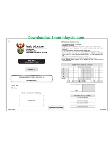
View all
Engineering Graphics and Design Grade 12 P1 2021 QP (Eng)
Grade 12 Engineering Graphics and Design Paper 1 question paper from the NSC November Exam 2021 (English), 6 pages. Read online or download the free PDF.
Engineering Graphic And Design · Grade 12 · NSC November Exam · 2021. Question paper, 6 pages. Read online or download the PDF.
- Subject
- Engineering Graphics and Design
- Grade
- Grade 12
- Document type
- Question paper
- Year
- 2021
- Exam period
- NSC November Exam
- Paper
- 1
- Curriculum
- CAPS
- Pages
- 6
- File size
- 2.1 MB
Free to read online, no sign-up needed
Loading document…
Loading document…
1 of 6
This exam
NSC November Exam 2021
Questions in this paper
Document textSearch extracted text and jump to a page.
Engineering Graphies and Design/P1
DBE/November 2021
Downloaded from hlayiso.com
Copyright reserved
LAND SURVEYORS CERTIFICATE OF THE =] SYNBOL LEGEND Contractors must veriy all dimensions ang | SUESTION 1: ANALYTICAL (CIVIL)
CORNER HEIGHTS AND BOUNDARY LENGTHS | 4 sHRUBBERY levels on site before commencing work.
CFE V AD GUBS CF SUNDER Architects to be notified immediately of any | Given:
CORNER HEIGHTS IN ] BOUNDARY LENGTHS | 2. PALM TREES discrepancies. The site plan of newly subdivided STAND 32 with new boundary and building lines as well as a proposed new house
METRES IN METRES and garage, a title panel and a table of questions. The drawing is not presented to the indicated scale.
A 351.5 ry 38,16 3. DECIDUOUS TREES ARCHITECTS SIGNATURE
B 349.2 BC 60 CLIENT'S SIGNATURE Instructions:
Complete the table below by neatly answering the questions, which refer to the accompanying drawing, title panel and
c 351.5 cD 38,16 civil content [30]
D 352.2 DA 60 ANSWER 20
In the space below, draw, in neat
E 3515 FD 33.8 freehand, the front view and top view QUESTIONS ANSWERS
F 3517 EG 33.8 118m CONCRETE WALL of the SANS 10743 graphical symbol |] What is the project number? 7
G 350.4 FG 34,56 , for a BIDET.
: : 2. | Who prepared the drawing? 1
STAND 18 5 3 | Whats the date of the first revision? 1
2000 BL Rel, 4 |Name the company that printed the drawing 1
i 5 | What size pipe is used for the new sewer line? 1
JE IE IE ale
a an 6 | What does the abbreviation /C at 1 stand for? 1
PROPOSED NEW New 7 | What type of tree is indicated at 2? 1
HOUSE GARAGE i!
8 | Name the constructed feature at 3. 1
al ?
al Few ot00 9 | What is indicated by the arrow at 4 1
8) || sewer ine
5] |b SEWERLINE 10 | Name the feature at 5. 1
I How many inspection eyes are there on the proposed ne
== 7 SUB-B OF ! 11 | pom nse Hon ey prop. ‘Ww 1
! g! STAND 32 jouse
| 16881 8 im 4g |/M what colour should drain and soil pipes be indicated on ,
| 353) 3 drainage installation drawings?
| £82 | ‘ADD NEW STORM
1885 | 20000 ee i 2 2021-0244 WATER DRAIN AT | |. | With reference to the building regulations, why should the a
7 L. aml LOWEST CORNER existing outbuilding be demolished now?
i 2000 BL ay 1 | 2021-01-23) INCRE way | 44 | What is the fall of the existing sewer line? 1
a - ;
& revision! DATE pescriprion | 45 | What is the shortest distance from the existing house to :
e | Austen Street in metres?
g With reference to the second revision, closest to which
! g CLASSIC DESIGN 46 | comer of SUB-B of STAND 32 should a new stormwater 1
ZI ARCHITECTS www.clasdes.co.za drain be placed?
STAND 309 @ |] stanp 34 om
I E CAPE TOWN Z With reference to the north point, what is the direction of P
| o! flow of the municipal sewer line?
2 PRINTED By DATE OF PRINT
\ 2 | DUPLEX PRINTING 2021-02-21 4a | In the space below (ANSWER 18), determine the perimeter of SUB-B of STAND 32, including the |,
SUB-A OF 2) DRAWING TITLE: new driveway, in metres.
STAND 32 | SITE PLAN
4g |In the space below (ANSWER 19), determine the total area of the proposed new house in square .
PROWECT metres
PROPOSED NEW HOUSE AND GARAGE |.) | In the space in the title panel (ANSWER 20), draw, in neat freehand, the front view and top view of |,
ON SUBDIVISION B OF STAND 32 FOR the SANS 10143 graphical symbol for a BIDET.
ROSS WATSON, 25 AUSTEN STREET,
\ PIKETBERG, 1965 TOTAL | 30
7X \ 3m PAVEMENT wi e
\ PROJECT NUMBER DRAWING NUMBER: ANSWER 18. Show ALL calculations. 45900 ANSWER 19. Show ALL calculations.
JBV-500W AAG-2121 t ul
EXISTING SEWER LINE —S
AUSTEN STREET 6mWIDE \. LAID AT 1: 40 DATE: DRAWN: CHECKED: | SCALE: 60 8
\ 2021-01-10] | JOHN WAYNE | 1; 350 ol S 8
a = REFERENCE CODE 3} | Cl “
MH MH oaR20e _ “N 2 EXAMINATION NUMBER
SITE PLAN $
SCALE 1: 350 3000 ~
4 x EXAMINATION NUMBER [2
Please tum over
Engineering Graphies and Design/P1
DBE/November 2021
%
‘6
Downloaded from hlayiso.com
QUESTION 2: INTERPENETRATION AND
DEVELOPMENT
Given:
© The top view and incomplete front view of a
connecting piece for a ventilation system. The
connecting piece consist of a right equilateral
triangular tube and a right regular hexagonal
tube, The axes of both tubes lie in a common
vertical plane.
© An auxiliary view of the triangular tube
Instructions:
Draw, to scale 1 : 1, the following views of the
two tubes:
2.1 The given top view
2.2 The right view
2.3 The complete front view, clearly showing
the curve of interpenetration
2.4 The development of the triangular tube.
Make edge 'S-S' the seam.
* Planning is essential.
* Show ALL hidden detail and folding lines.
Show ALL construction. [38]
; |
if
36 |
90
MAKE EDGE S-S THE SEAM
ASSESSMENT CRITERIA
41 |TOP VIEW 6
2 |RIGHT VIEW 5
3 |FRONT VIEW 164
4 |DEVELOPMENT 104
PENALTIES (-)
TOTAL| 38
EXAMINATION NUMBER
EXAMINATION NUMBER [3
Copyright reserved
Please tum over
Engineering Graphies and Design/P1
%
‘6
PP.
Downloaded from hlayiso.com
DBE/November 2021
QUESTION 3: PERSPECTIVE
Given:
Three views of the inside of a dressing room
and the information needed to draw a two-point
perspective drawing
PP - Picture plane
HL - Horizon line
GL - Ground line
SP - Station point
Instructions:
Complete the perspective drawing.
* Align the drawing sheet with the ground
line (GL).
* Determine and label the vanishing points.
¢ Show ALL construction.
* NO hidden detail is required. [40]
HL
WINDOW
GL
winDow
T
i
i
1
i
as
!
1
i
i
1
1
i
i
1
i
i
i
i
1
i
i
1
1
i
i
i
i
i
i
i
1
i
i
L
Copyright reserved
ASSESSMENT CRITERIA
1 | CONSTRUCTION 6
WALLS + CUPBOARD +
2 | winoow
20
3 | TABLE + MIRROR 14
PENALTIES (-)
TOTAL} 40
EXAMINATION NUMBER
EXAMINATION NUMBER [4
Please tum over
Engineering Graphies and Design/P1
SO
r
2600
ROOF LINE
INCOMPLETE FLOOR PLAN
10 mm CEILING BOARD ON 40 x 40 mm
BRANDERING STRIPS @ 400 mm cic
Downloaded from hlay
DOOR OPENING
ROOF CAP
RIDGE COVER
150 x 100 mm GUTTER ON
300 x 20 mm FASCIA BOARD
@100 mm RWDP THAT STOPS 50 mm
ABOVE THE 400 x 150 mm GULLEY
WINDOW OPENING
FINISHED FLOOR LEVEL
GROUND LEVEL
VERANDA FLOOR LEVEL
FEATURES
D1 SLIDING DOOR
D2 DOOR
wi WINDOW
w2 WINDOW
wW3 WINDOW
FIXTURES
we TOILET
WB WASH BASIN
SH SHOWER
S SINK
ELECTRICAL FITTINGS
1. ONE-WAY SWITCH - SINGLE-POLE
2. ONE-WAY SWITCH - DOUBLE-POLE
3. FLUORESCENT LIGHT 3 x 45 W
4. CEILING LIGHT
5. WALL-MOUNTED LIGHT
6. SWITCHED SOCKET OUTLET
NOTE:
THE ARROW SHOWS THE LIGHT
CONNECTION TO THE SWITCH.
Ag
F280.
F280 oy, e209,
400 elds00 ere fu -
80 x 200 mm
SCHEMATIC DIAGRAM OF LINTELS ABOVE —_-|
AROOF TRUSS AT A-A ALL WINDOW
‘AND DOOR
OPENINGS
ROOF NOTES: 3
20° ROOF PITCH &
114 x 40 mm ROOF TRUSSES ON
114 x 40 mm WALL PLATES
500 mm ROOF OVERHANG TO END OF Flown eevee
ROOF TRUSS | ° 8
FS) 2
20 mm FIBRE CEMENT ROOF SHEET t
N75 50 mm PURLINS @ 660m co exouno ever Lit
8 2 8
300 x 20 mm FASCIA BOARD WITH | 8
150 x 100 mm GUTTER ON ALL SIDES [ ]
INCOMPLETE FOUNDATION,
EXTERNAL WALL AND
VERANDA DETAIL
BEDROOM:
FLOOR FINISHES
CARPET
BATHROOM: TILES
com
RAINWATER
ITEMS
100
— LIVING ROOM: WOOD ~
> ca] KITCHEN: © TILES. =
vercuen VERANDA: TILES
w00 |]
ROOM AND AREA DESIGNATIONS
DOOR AND WINDOW SCHEDULE
TOFIT
TOFIT 50 2200
OFT gf - 2
A B A g
~~
600_)- WINDOW (W1)
600)
SSS DOOR FRAME i 71 525
SLIDING DOOR (D1) 2 ~~ AND DOOR (02) | rT
WINDOW NOTES: SH
. PENING SIDE g| s|
* B= FIXED PANEL Fe B||A S|
* ALL FRAMES = 50 mm. 8
+ 150 x 20 mm FIBRE CEMENT SILL UNDER ALL
WINDOWS 1100
WINDOW (Ww2) WINDOW (w3)
ELECTRICAL SYMBOLS
a al fo) fo) ROOF COMPONENTS
i < 8 fo} — 300 x 20 mm FASCIA BOARD
ul 150 x 100 mm GUTTER
1x45 W
mo x REE 300
+ ea ROOF CAP AND RIDGE COVER
FIXTURES
{FLOOR LEVEL
S
WASH BASIN
(WB)
TOILET
(we)
900
‘SHOWER
(s) (SH)
Copyright reserved
QUESTION 4: CIVIL DRAWING
Given:
* The incomplete north elevation of a new house, showing
the walls, the window and door openings, the veranda, the
roof and labels
* The incomplete floor plan showing the walls, positions of
the doors, windows, fixtures and electrical layout
* A schematic diagram of a roof truss at A-A and roof notes
© The incomplete foundation, external wall and veranda detail
* Room and area designations as well as floor finishes
* A table of rainwater items
* A door and window schedule
* A table of electrical symbols
* A table of roof components
* A table of fixtures
* The incomplete floor plan and the ground line of the new
house, drawn to scale 1 : 50, and the incomplete
foundation and a break line for the detailed section, drawn
to scale 1 : 20, on page 6.
Instructions:
Answer this question on page 6.
4.1 Using the given incomplete floor plan, draw, to
scale 1 : 50, the following views of the new house:
4.1.1 THE COMPLETE FLOOR PLAN
Add the following features to the drawing:
* ALL doors and windows
* ALL fixtures as indicated by the abbreviations
* ALL electrical fittings as indicated by the numbers
* The complete roof lines
* ALL hatching detail
4.1.2 THE COMPLETE NORTH ELEVATION
Show the following features on the drawing:
* The outside walls, veranda, window and door detail
* The roof detail, including the fascia boards, gutters,
rainwater down-pipe and gulley
© The finished floor level
Using the given foundation and break line on page 6,
draw, to scale 1: 20, a DETAILED SECTION on cutting
plane A-A of the area in the ellipse shown on the
incomplete floor plan
Show the following features on the drawing:
The complete foundation, external wall and window
detail
*The roof detail, including the fascia board, gutter,
rainwater down-pipe and gulley
* The wash basin to the west of cutting plane A-A
* ALL hatching detail. ONLY the substructure hatching
may be drawn in neat freehand.
42
Label the following:
© The north elevation
© The floor finishes
* Ground level, finished floor level and damp-proof course
(use the correct abbreviations and show it on ALL the
relevant views)
NOTE:
ALL drawings must comply with the guidelines and
graphical symbols as contained in the SANS 10743. [92]
[5]
Please tum over
DBE/November 2021
Engineering Graphies and Design/P1
Downloaded from hlayiso.com
y
ge?
GL
TT RWOP[—]
3] |
a |
|
| |
| |
| |
| LIVING ROOM BEDROOM |
| |
| w!
| Z|
| u |
fe)
| 9 |
| |
| |
| — |
| |
| |
| fr] |
| 2 fh |
| |
| |
| rocco
|
| VERANDA KITCHEN A |
| BATHROOM
| I
| |
| |
i; U so
| |
bo RWOP
FLOOR PLAN A
SCALE 1 : 50
Copyright reserved
SECTION A-A
SCALE 1: 20
DBE/Noverber 2021
MARK
ALLOCATION FOR FOR OFFICIAL USE ONLY
SECTION OF ROOF
INCORRECT SCALE(S)
A USED
B NON-ALIGNMENT OF
VIEWS:
c
5 VIEW(S) ROTATED
E SECTION VIEWED
INCORRECTLY
F
INCORRECT
G LETTERING
H
TOTAL TOTAL
ASSESSMENT CRITERIA
FLOOR PLAN
POSSIBLE | oBTANED | SIGN] MODERATED
DOORS «
1 | wnoows 13
FOTURES ©
2 | ROOF Lines: 1
3 |etectrica | Bd
4 | Harcuns 3
5 | vases 23
SUBTOTAL 38
NORTH ELEVATION
ROOF +
1 | RwoP’ 103
GuiLey
WALLS
2 |stepven | 4
DOOR
3 | winoow 6
4 | vases 1
SUBTOTAL 213
DETAILED SECTION
1 |roorveme | 134
SAB, WALL,
2 |wnoows” | 42
Basiv
3 [uscune | 5g
4 | vaseis 13
SUBTOTAL 323
TOTAL 92
PENALTIES (-)
GRAND TOTAL
EXAMINATION NUMBER
EXAMINATION NUMBER [6
Study this subject
Recommended for this subject
Question paper
Engineering Graphics and Design Grade 12 P1 2021 QP (Afr)
Question paper
Engineering Graphics and Design Grade 12 P1 NSC June 2021 QP
Question paper
Engineering Graphics and Design Grade 12 P1 NSC June 2021 QP
Question paper
Engineering Graphics and Design Grade 12 P1 2023 QP (Eng)
Question paper
Engineering Graphics and Design Grade 12 P1 2022 QP (Eng)
Question paper
Engineering Graphics and Design Grade 12 P1 2020 QP (Eng)
More from Grade 12 Engineering Graphics and Design
Memorandum
Engineering Graphics and Design Grade 12 P1 2025 Memo
Memorandum
Engineering Graphics and Design Grade 12 P2 2025 Memo (Eng)
Memorandum
Engineering Graphics and Design Grade 12 P2 2025 Memo
Memorandum
Engineering Graphics and Design Grade 12 P2 2024 Memo (Eng)
Memorandum
Engineering Graphics and Design Grade 12 P1 2023 Memo (Afr)
Question paper