
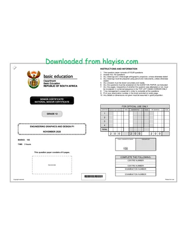
basic education
uf Department:
« )) Basic Education
“4 REPUBLIC OF SOUTH AFRICA
NATIONAL
SENIOR CERTIFICATE
( ENGINEERING GRAPHICS AND DESIGN P1 2)
|
(e NOVEMBER 2024 7)
MARKS: 100
TIME: 3 hours
This question paper consists of 6 pages.
| |
| |
| |
| Barcode label |
| |
| |
| |
DO NOT FOLD THE QUESTION PAPER IN HALF.
Copyright reserved
Confidential
INSTRUCTIONS AND INFORMATION
This question paper consists of FOUR questions.
Answer ALL the questions.
ALL drawings are in first-angle orthographic projection, unless otherwise stated.
ALL drawings must be prepared using pencil and instruments, unless otherwise
stated.
ALL answers must be drawn accurately and neatly.
ALL the questions must be answered on the QUESTION PAPER, as instructed.
ALL the pages, irrespective of whether the question was attempted or not, must
be re-stapled in numerical sequence in the TOP LEFT-HAND CORNER ONLY.
8. Time management is essential in order to complete all the questions.
9. Print your examination number in the block provided on every page.
10. Any details or dimensions not given must be assumed in good proportion.
BONS
NO
FOR OFFICIAL USE ONLY
QUESTION }| MARKS OBTAINED | } | SIGN MODERATED 3] SIGN RE-MARKING 3] SIGN
1
2
3
4
TOTAL
2|0/0 2|0/0 2|0|0
FINAL CONVERTED MARK CHECKED BY
100
COMPLETE THE FOLLOWING:
CENTRE NUMBER
CENTRE NUMBER
EXAMINATION NUMBER
EXAMINATION NUMBER
Please tun over
Skip to contentAll 2024 papers 
View all
Engineering Graphics and Design Grade 12 P1 2024 QP (Eng)
Grade 12 Engineering Graphics and Design Paper 1 question paper from the November 2024 NSC (English), 6 pages. Read online or download the free PDF.
Engineering Graphic And Design · Grade 12 · November 2024 NSC · 2024. Question paper, 6 pages. Read online or download the PDF.
- Subject
- Engineering Graphics and Design
- Grade
- Grade 12
- Document type
- Question paper
- Year
- 2024
- Exam period
- November 2024 NSC
- Paper
- 1
- Curriculum
- CAPS
- Pages
- 6
- File size
- 2.4 MB
Free to read online, no sign-up needed
Loading document…
Loading document…
1 of 6
This exam
November NSC 2024
Questions in this paper
Document textSearch extracted text and jump to a page.
Engineering Graphics and Design/P1
NSC Confidential
DBE/November 2024
(/g_ [PAND SURVEYORS CERTIFICATE OF THE ‘SYMBOL LEGEND:
Ce CORNER HEIGHTS AND BOUNDARY
$ LENGTHS OF STAND 3114 CACTUS PLANT
BOUNDARY
CORNER HEIGHTS
LENGTHS IN WILLOW TREE
INMETRES MILLIMETRES
a | 1718 | aa] 76770 SHRUBBERY
B | 11721 | ec] 63940 FRENCH DRAIN
ce | 1739 | co | 27160 1,8 m PALISADE
Tae FENCE
° S| DE | 62590 2m HIGH ELECTRIC
e | t7az [er | 27150 FENCE
F 1172.3 | FA 63340 ACCOMMODATION:
CHALET = 4 GUESTS EACH
LODGE =6 GUESTS
EXISTING
NEW4,5m 5m WIDE
WIDE VEHICLE svanp VEHICLE MUNICIPAL
ENTRANCE ENTRANCE SEWERAGE LINE
waastecer | fou
a eS es et
4 3000 BL
fsa-| |=
3112
PROPOSED:
NEW CARPORT]
NEW DRIVEWAY
FINISHED WITH
}— 500 x 500 mm
PAVERS x
32000 L
‘SWIMMING POOL
STAND
EXISTING
PARKING AREA,
Ie
CHALET 1
2 |
IE
3114
EXISTING DRIVEWAY
a}
EXISTING
CARPORT
Ee
7
NEW SEPTIC TANK TO —
ENGINEERING
SPECIFICATIONS
‘PRIVATE GAME 4
RESERVE
SITE PLAN
SCALE 1: 900
NOTE:
Contractors must verify all dimensions and
levels on site before commencing work.
Architects to be notified immediately of any
discrepancies.
ARCHITECT'S SIGNATURE:
CLIENTS SIGNATURE:
QUESTION 1: ANALYTICAL (CIVIL)
Given:
The site plan of an existing resort with a proposed new lodge and deck, as well as a new carport, a title panel and a
table of questions. The drawing is not presented to the indicated scale.
Instructions:
Complete the table below by neatly answering the questions, which refer to the accompanying drawing, title panel and
ANSWER 20 civil content. [30]
In the space below, draw, in neat
freehand, the SANS 10143
graphical symbol for QUESTIONS ANSWERS
(a) The front view of a BIDET 7
(b) An electrical REGULATING 1 | What does the number 0214-59 refer to? 1
SWITCH/DIMMER 2 | Who is the client? 1
(a) BIDET 3 | Who printed the drawing? 1
4 | In which town is the architectural firm situated? 1
5 | What was the second revision? 1
6 | How high is corner D above sea level in metres? 1
7 |Name the feature at 1. 1
(b) Electrical REGULATING 8 | Name the natural feature at 2 1
SWITCH/DIMMER 9 | What is the height of the feature at 3 in millimetres? 1
10 | What must happen to the features at 4? 1
11 [Name the symbol at 5. 1
12 | What is the finish on the new driveway? 1
13 | What does the abbreviation BIC on floor plans stand for? 1
2 | zertwa0z3 | aod wareR tank | 44 |!n what colour must new drain pipes be indicated on ;
drainage installation drawings?
+ | s7iazoes | MOVE FRENCH | 4 | What is the shortest distance from the proposed new :
DRAIN carport to the boundary line with STAND 3112 in metres?
revision! DATE vescriprion | 46 | With reference to the north point, in what direction does the :
sewerage flow in the municipal sewerage line?
HSJ ARCHITECTS 47 | What is the proposed total number of guests that would be :
27 ORIBI DRIVE www safariplus.coza accommodated at the resort?
KRUGER HILL 019 405 9777
POLOKWANE 18 | In the space below (ANSWER 18), determine the total perimeter of the area ABCF in metres. 3
4059
49 |In the space below (ANSWER 19), determine the total area of the new lodge and deck in square .
PRINTEDBY: DATE OF PRINT metres.
CHEETAH PRINTERS 26/10/2023 29 | nthe space in the title panel (ANSWER 20), draw, in neat freehand, the SANS 10143 graphical a
DRAWING TILE: symbol for: (a) the front view of a BIDET, and (b) an electrical REGULATING SWITCH/DIMMER
SITE PLAN TOTAL| 30
PROUECT
PROPOSED NEW LODGE, DECK ANSWER 18 ANSWER 19
AND CARPORT FOR MR D BRITS, Show ALL calculations. 17500, Show ALL calculations.
(ON STAND 3114, 700
7 NYALA STREET, TUGELA RIVER, fay
LIMPOPO Ss —
PROJECT NOWEER BRATING NUWBER 38 Bs
40-1302 0214-59 & gq 8
DATE: DRAWN: ‘CHECKED: J
29109/2023| STEVEN | PALESA \ EX
foro, g
REFERENGE CODE SCALE g
FmA2614/. 13900 “| EXAMINATION NUMBER
EXAMINATION NUMBER [2
Copyright reserved
Please tum over
Engineering Graphics and Design/P1
NSC Confidential
DBE/November 2024
QUESTION 2: SOLID GEOMETRY
Given: ..
© The front view of a right regular hexagonal pyramid
and a right square prism
© The top view of the right regular hexagonal
pyramid, with the axes and an auxiliary view for the
right square prism
* Cutting plane S-S
Specifications:
* The lower base of the right square prism rests
against the right side triangular face of the
hexagonal pyramid
* Both solids are cut by cutting plane S-S
Instructions:
Draw, to scale 1 : 4, the following views showing both
solids:
2.1 The given front view
2.2 A sectional top view
2.3 A sectional left view
* Planning is essential.
* Show ALL construction.
* Show ALL hidden detail. [38]
50.
22)
ASSESSMENT CRITERIA
41 |FRONT VIEW 74
2 |SECTIONALTOP View |164
3 |SECTIONALLEFT VIEW | 14
PENALTIES (-)
TOTAL| 38
EXAMINATION NUMBER
EXAMINATION NUMBER, [3
Copyright reserved
Please tum over
Engineering Graphics and Design/P1
NSC Confidential
DBE/November 2024
PP
QUESTION 3: PERSPECTIVE
Given:
Three views of an A-frame house on blocks and the
information needed to draw a two-point perspective drawing
PP - Picture plane
HL - Horizon line
GL - Ground line
SP - Station point
Instructions:
Complete the perspective drawing
* Align the drawing sheet with the ground line (GL).
* Determine and label the vanishing points.
* Show ALL construction
* Show depth at the door and windows.
© NO internal or hidden detail is required. [40]
ASSESSMENT CRITERIA
1 | CONSTRUCTION 6
FLOOR + STEPS 12
WINDOWS + DOOR 93
2
3
4 | ROOF 7
5
ARC 53
PENALTIES (-)
TOTAL | 40
HL
GL
HL
—---4
GL
EXAMINATION NUMBER
EXAMINATION NUMBER [4
Copyright reserved
Please tum over
Engineering Graphics and Design/P1
NSC Confidential
DBE/November 2024
o=———_
300 x 80 mm BARGE BOARD
ROOF CAP
RIDGE CAP
150 x 100 mm GUTTER ON
200 x 20 mm FASCIA BOARD
WINDOW OPENINGS
DOOR OPENING
[315
DOUBLE SWING DOOR OPENING
150 x 300 mm CONCRETE STEP
ru
FINISHED FLOOR LEVEL
INCOMPLETE NORTH-WEST ELEVATION
ROOF LINE.
por7 7-7 SSS ------<9
ROOF NOTES:
20° ROOF PITCH
PLATES
PURLINS @ 1000 mm cle
PAST FASCIA BOARDS
200 x 20 mm FASCIA BOARDS WITH
150 x 100 mm GUTTERS ON ALL SIDES
STRIPS @ 300 mm ole
INCOMPLETE SCHEMATIC DIAGRAM OF
AROOF TRUSS AT CUTTING PLANE A-A
120 x 40 mm ROOF TRUSSES ON 120 x 40 mm WALL
350 mm ROOF OVERHANG TO END OF ROOF TRUSS
40 mm CORRUGATED ROOF SHEET ON 80 x 50 mm
300 x 80 mm BARGE BOARDS ON GABLE END 150 mm
10 mm CEILING BOARDS ON 40 x 40 mm BRANDERING
ye
woo ST
GROUND LEVEL
FEATURES
D1 DOUBLE SWING DOOR
D2 DOOR
wi WINDOW
w2 WINDOW
w3 WINDOW
FIXTURES
S SINK
SH SHOWER
we TOILET
WB WASHBASIN
ELECTRICAL FITTINGS
1. ONE-WAY SWITCH - SINGLE-POLE
2. ONE-WAY SWITCH - DOUBLE-POLE
3. FLUORESCENT LIGHT 2 x 40 W
4. CEILING LIGHT
5. SWITCHED SOCKET OUTLET
6. DISTRIBUTION BOARD
NOTE:
‘THE ARROW SHOWS THE LIGHT
CONNECTION TO THE SWITCH.
200
200 x 80 mm nl
LINTELS ABOVE
ALL DOOR
AND WINDOW
OPENINGS
2100
2600
at
GROUND
300,
200)
LEVEL
CONCRETE PATIO
450 450.
Ce
|
INCOMPLETE FOUNDATION, EXTERNAL WALL
AND PATIO DETAIL
i
is]
RY
Fl
‘LOOR FINISHES
1 1. OPENAREA: TILE
3 2. BATHROOM: — TILE
3. BEDROOM CARPET
ROOM DESIGNATIONS
DOOR AND WINDOW SCHEDULE
50
a7 TOFIT y 4 Tort yy 1500 f 800,
3
8
2 A
a
ol B e
=| 3 B
WINDOW (w1)
600
4 *
WINDOW (W3}
DOUBLE SWING DOOR SINGLE DOOR s (w3)
AND FRAME WITHTWO AiR ros
DOORS (D1) (2) 8
WINDOW NOTES: A
* A= OPENING SIDE SS
«8 = FIXED PANEL WINDOW (wa)
ALL FRAMES = 50 mm THICK
© 200 x 20 mm FIBRE CEMENT SILL UNDER ALL WINDOWS
ROOF COMPONENTS ELECTRICAL SYMBOLS
300
EY ROOF CAP AND RIDGE CAP a
pC — =
Lome)
300 x 80 mm BARGE BOARD b —
= 200 x 20 mm FASCIA BOARD 7
150 x 100 mm GUTTER
mont X Xf
o 80 x 50 mm PURLINS
FIXTURES
1200
500 y a us 500
oe a -
e 3 S| ed
ENP 3) 500) Sy 80 38
& Lama — L FLOOR
\ = LEVEL
+. x x
8 8 "NL be s
X
X
TOILET SINK SHOWER WASHBASIN
(we) 6) (SH) (we)
QUESTION 4: CIVIL DRAWING
Given:
© The incomplete north-west elevation of a new house, showing
the walls, the window and door openings, the patio and step,
roof and labels
* The incomplete floor plan showing the walls, roof line, patio,
step, positions of the doors and windows, fixtures and electrical
layout
* An incomplete schematic diagram of a roof truss at cutting
plane A-A and roof notes
The incomplete foundation, external wall and patio detail
Room designations and floor finishes
A door and window schedule
A table of roof components
A table of electrical symbols
A table of fixtures
The incomplete floor plan and position of the ground level of
the new house, drawn to scale 1 : 50, and the incomplete
foundation and break lines for the detailed section, drawn to
scale 1 ; 20, on page 6
Instructions:
Answer this question on page 6.
4.1. Using the given incomplete floor plan and ground level, draw,
to scale 1 : 50, the following views of the new house:
4.1.1 THE COMPLETE FLOOR PLAN
Add the following features to the drawing:
* ALL doors and windows
* ALL fixtures as indicated by the abbreviations
* ALL electrical fittings as indicated by the numbers
* ALL hatching detail
4.1.2 THE COMPLETE NORTH-WEST ELEVATION
Show the following features on the drawing:
* The walls, windows, doors (with all three doors in the closed
position), patio and step detail
© The roof detail including fascia board, barge boards and
gutter
* The finished floor level
Using the incomplete foundation and break lines on page 6,
draw, to scale 1: 20, a DETAILED SECTION on cutting
plane A-A of the area in the ellipse shown on the incomplete
floor plan.
Show the following features on the drawing:
* The complete foundation, external wall, slab, patio and
window detail
© The roof detail including the fascia board and gutter
© The door and frame, roof, fascia board and gutter detail, to
the left (north-east) of cutting plane A-A
* ALL hatching detail. ONLY the substructure hatching may
be drawn in neat freehand.
4.2
Label the following:
The floor finishes
* Ground level, finished floor level and damp-proof course (use
the correct abbreviations and show them on ALL relevant
views)
NoTI
ALL drawings must comply with the guidelines and graphical
symbols as contained in SANS 10143. [92]
[5]
Copyright reserved
Please tum over
Engineering Graphics and Design/P1
NSC Confidential
DBE/November 2024
SECTION A-A
SCALE 1: 20
MARK
pongo FOR OFFICIAL USE ONLY
SECTION OF ROOF | ycoRRECT
A SCALE(S) USED
3 NON-ALIGNMENT OF
VIEWS
c VIEW(S) ROTATED
® SECTION VIEWED
E INCORRECTLY
F INCORRECT
LETTERING
6
H
J
TOTAL TOTAL
ASSESSMENT CRITERIA
GL
FLOOR PLAN
NORTH-WEST ELEVATION possiate | ostainen | sicn | monerateD
1 | nivoows | 14
2 | Fixtures 7
3 |etecrrica | 74
4 | Lssets 2
5 | natcxna 3
SUBTOTAL 333
NORTH-WEST ELEVATION
3 inmoows | 112
4 [uss 3
SUBTOTAL 233
DETAILED SECTION
41} ROOF DETAIL 13
BEDROOM 2 |susrwa | 7
3 | HatcHING 6s
5 | uss 13
SUBTOTAL 35
oe TOTAL 92
PENALTIES (-)
GRAND TOTAL
FLOOR PLAN
SCALE 1: 50
EXAMINATION NUMBER
EXAMINATION NUMBER [6
Copyright reserved
Study this subject
Recommended for this subject
Question paper
Engineering Graphics and Design Grade 12 P1 2023 QP (Eng)
Question paper
Engineering Graphics and Design Grade 12 P1 2022 QP (Eng)
Question paper
Engineering Graphics and Design Grade 12 P1 NSC June 2021 QP
Question paper
Engineering Graphics and Design Grade 12 P1 NSC June 2021 QP
Question paper
Engineering Graphics and Design Grade 12 P1 2021 QP (Afr)
Question paper
Engineering Graphics and Design Grade 12 P1 2020 QP (Eng)
More from Grade 12 Engineering Graphics and Design
Memorandum
Engineering Graphics and Design Grade 12 P1 2025 Memo
Memorandum
Engineering Graphics and Design Grade 12 P2 2025 Memo (Eng)
Memorandum
Engineering Graphics and Design Grade 12 P2 2025 Memo
Memorandum
Engineering Graphics and Design Grade 12 P2 2024 Memo (Eng)
Memorandum
Engineering Graphics and Design Grade 12 P1 2023 Memo (Afr)
Question paper