
Downloaded from hlayiso.com
INSTRUCTIONS AND INFORMATION
1. This question paper consists of FOUR questions.
2. Answer ALL the questions.
3. ALL drawings are in third-angle orthographic projection, unless otherwise stated.
4. ALL drawings must be completed using instruments, unless otherwise stated.
GRADE 12 5. ALL answers must be drawn accurately and neatly.
6. ALL the questions must be answered on the QUESTION PAPER as instructed.
7. ALL the pages must be re-stapled in numerical sequence, irrespective of
whether the question was attempted.
8. Time management is essential in order to complete all the questions.
9. Print your examination number in the block provided on every page.
10. Any details or dimensions not given must be assumed in good proportion.
NATIONAL
SENIOR CERTIFICATE
FOR OFFICIAL USE ONLY
QUESTION MARKS OBTAINED ½ SIGN MODERATED ½ SIGN
GRADE 12 1
2
3
ENGINEERING GRAPHICS AND DESIGN P2 4
TOTAL
FEBRUARY/MARCH 2015
2 0 0 2 0 0
MARKS: 100
FINAL CONVERTED MARK CHECKED BY
TIME: 3 hours
_______
100
This question paper consists of 6 pages. COMPLETE THE FOLLOWING:
CENTRE NUMBER
CENTRE NUMBER
EXAMINATION NUMBER
EXAMINATION NUMBER
*BASIC-EDUCATION*
Copyright reserved
Please turn over
Skip to contentAll 2015 papers 
View all
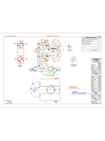
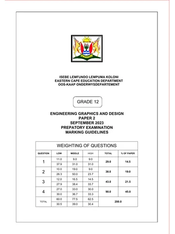
Engineering Graphics and Design Grade 12 P2 2015 QP (Eng)
Grade 12 Engineering Graphics and Design Paper 2 question paper from the NSC Supplementary 2015 (English), 6 pages. Read online or download the free PDF.
Engineering Graphic And Design · Grade 12 · NSC Supplementary · 2015. Question paper, 6 pages. Read online or download the PDF.
- Subject
- Engineering Graphics and Design
- Grade
- Grade 12
- Document type
- Question paper
- Year
- 2015
- Exam period
- NSC Supplementary
- Paper
- 2
- Curriculum
- CAPS
- Pages
- 6
- File size
- 1.3 MB
Free to read online, no sign-up needed
Loading document…
Loading document…
1 of 6
This exam
NSC Supplementary 2015
- Paper 1Question paper
- Paper 2Question paperMemo
Questions in this paper
Document textSearch extracted text and jump to a page.
Engineering Graphics and Design/P2
Downloaded frgm hlayiso.com
DBE/Feb.-Mar. 2015
aa
200
12 HOLE
@26 x 5 SPOT FACE
QUESTION 1: ANALYTICAL (MECHANICAL)
Given:
A front view, top view and right view of a box and gland assembly, detailed drawing of the flange, a title block and
a table of questions. The drawings have not been prepared to the indicated scale.
Instructions:
Complete the table below by neatly answering the questions, which all refer to the accompanying drawings and
the title block.
[30]
QUESTIONS
ANSWERS
On what date was the drawing approved?
What is the title of the assembly?
What scale is indicated for the drawing?
What material is used to manufacture the bush?
On what date was the revision done?
What is the drawing number?
What would VIEW 3 be called?
What type of section is shown in VIEW 1?
What part is used to protect the flange surface when the
nut is being tightened?
10
Name the part at R
11
Name the feature at S.
12
Name the feature at T.
8
13,
How many surfaces need to be machined?
14
Give the complete dimensions at: A
15,
Determine the complete dimensions at: c
| [18
With reference to the tolerance, determine the maximum
dimension at E.
258
VIEW 1
ALL DIMENSIONS ARE IN MILLIMETRES
SCALE: 1:2
DRAWING PROGRAM: AUTOCAD 2013
FINISH: POLISHED
FILE NAME: ANAS15.dwg
QUANTITY: 325 UNITS
DRAWING No. BG-15/4
MACHINING: MILLING
17
With reference to the tolerance, determine the minimum
dimension at E.
18
Insert the cutting plane on VIEW 3 and label it A-A.
19
VIEW 3
In the space provided below, draw, in neat freehand, the symbol for the projection system
used,
TOTAL
30
PARTS LIST
ANSWER 19
PART
MATERIAL
QUANTITY
BASE
CAST IRON 1
UNLESS OTHERWISE SPECIFIED, ALL TOLERANCES ON DIMENSIONS
ARE +0,15, ALL UNSPECIFIED RADII ARE R3.
2,
FLANGE
MILD STEEL 1
1. INSERT SPOT FACE
2014/02/03
sTUD
MILD STEEL 2
PEWIJO
ENGINEERING
15 FABRICIA ROAD
KLISSERVILLE
KIMBERLEY
8301
F051 6273 849
REVISIONS
DATE
SHAFT
HARDENED STEEL 1
DRAWN: ALFA
2014/01/01
BUSH
RUBBER 1
CHECKED: BRAVO
2014/02/02
WASHER
MILD STEEL 2
TITLE
BOX AND GLAND
APPROVED: ZERO
2014/03/03
NUT MILD STEEL 2
Copyright reserved
SYMBOL
EXAMINATION NUMBER
EXAMINATION NUMBER
[2
Please tum over
Engineering Graphics and Design/P2
Downloaded frgm hlayiso.com sch
Copyright reserved
QUESTION 2: Loc!
HELIX
Given:
© The left view of a square spring with RS indicating starting
position
* The position of centre point T on the drawing sheet
Specifications:
* Pitch =72
© Spring profile = 24x24
* Direction = Right-handed
Instructions:
Draw, to scale 1 : 1, the following:
2.1 The given left view with point T as reference
2.2 The front view for TWO turns of the square spring
* Show ALL necessary construction.
* No hidden detail is required [37]
ASSESSMENT CRITERIA
4 | GIVEN+ CENTRE LINES | 4s
+ STARTING POINT 2
2 | CONSTRUCTION 8
3 | OUTSIDE POINTS + 145
CURVE + QUALITY 2
4 | INSIDE POINTS + cURVE | 4,
+ QUALITY
PENALTIES ()
TOTAL} 37
EXAMINATION NUMBER
EXAMINATION NUMBER [3
Please tum over
Engineering Graphics and Design/P2
Downloaded frgm hlayiso.com sch
aa
Copyright reserved
QUESTION 3: ISOMETRIC DRAWING
Given:
© The front view, top view and left view of a machine switch
with cutting plane A-A
* The position of point P on the drawing sheet
Instructions:
Using scale 1: 1, convert the orthographic views of the
machine switch into a sectional isometric drawing on cutting
plane A-A.
* Make P the lowest point of the drawing.
* Show ALL necessary construction.
NO hidden detail is required [39]
40
410
30 90.
36. 110.
ASSESSMENT CRITERIA
1 | AUX. VIEW+PLACING | 3
ISOMETRIC +
1
NON-ISOMETRIC LINES: 16
ISO' CIRCLES + CIRCLE
CONSTRUCTION 5
4 | SECTIONED SURFACES | 11
5 | HATCHING 34
PENALTIES (-)
TOTAL | 39
EXAMINATION NUMBER
EXAMINATION NUMBER [4
Please tum over
Engineering Graphics and Design/P2
Downloaded frgm hlayiso.com sch
aa
12
SEAL [2]
—} 4
ee
ELUPSE
a
100
78
930
|
T
i
|
tra
a2
BASE [3]
EXPLODED ISOMETRIC DRAWING
M12
M12 NUT [7]
Copyright reserved
58
SHAFT [1]
20
44 @4
Polo
——a
GUIDE PIN [4]
\R10
| ox
WASHER [6]
QUESTION 4: MECHANICAL ASSEMBLY
Given:
* The exploded isometric drawing of the parts of a distribution
box lock assembly, showing the position of each part relative
to all the others
* Orthographic views of each of the parts of the distribution box
lock assembly
Instructions:
* Answer this question on page 6.
* Draw, to scale 2 : 1 and in third-angle orthographic projection,
the following views of the assembled parts of the distribution
box lock assembly:
4.1 A sectional front view on cutting plane A-A, as seen
from the direction of the arrow shown on the exploded
isometric drawing. The cutting plane, which passes
vertically through the centre of the assembly, is shown
on the right view of the base (part 3).
4.2 The right view
* ALL drawing must comply with the guidelines contained in the
SANS 10111
NOTE:
* Show THREE faces and ALL necessary construction of the
M12 nut.
Show ALL necessary construction of the ellipse.
Show ALL necessary construction of the triangle.
* Add cutting plane A-A to the drawing.
NO hidden detail is required. [94]
PARTS LIST
PART QUANTITY MATERIAL
4 | SHAFT 1 STAINLESS STEEL
2 | SEAL 1 RUBBER
3 [BASE 1 CAST IRON
4 | GUIDE PIN 1 MILD STEEL
5 | LOCKING LEVER 1 MILD STEEL
6 | WASHER: 1 MILD STEEL
7 [12 NUT 1 MILD STEEL
ENGINEERING CC wow jpwengineering,co.za
DISTRIBUTION BOX LOCK
ALL DIMENSIONS ARE | ALL UNSPECIFIED © 4
INMILLIMETRES RADII ARE R3. BI
Please tum over
vovnn apna Downloaded frgm hlayiso.com
DBE/Feb.-Mar. 2015
PENALTIES
NOT IN THIRD ANGLE
INCORRECT OVERALL SCALE
INCORRECT HATCHING
TOTAL PENALTIES (-)
ASSESSMENT CRITERIA
SECTIONAL FRONT VIEW
1 | sHAFT 47}
2 | SEAL 2
3 | BASE 184
4 | GUIDE PIN 2s
5 | LOCKING LEVER 7
6 | WASHER, 2d
7 | M12 NUT 6}
SUBTOTAL 564
RIGHT VIEW
1 | SHAFT 5
2 | M12 NUT 4
3 | WASHER 1
4 | LOCKING LEVER 43
5 | BASE 9
6 | GUIDE PIN 1
7 | CUTTING PLANE 3
SUBTOTAL 27d
GENERAL
1 | CENTRE LINES 4
2 | ASSEMBLY 6
SUBTOTAL 10
TOTAL | 94
TOTAL PENALTIES (-)
FINAL TOTAL
EXAMINATION NUMBER
(NN Saunenaiaes ——T8
Study this subject
Recommended for this subject
Question paper
Engineering Graphics and Design Grade 12 P2 2015 QP
Question paper
Engineering Graphics and Design Grade 12 P2 2015 QP (Eng)
Question paper
Engineering Graphics and Design Grade 12 P2 2015 QP (Afr)
Question paper
Engineering Graphics and Design Grade 12 P2 2014 QP (Eng)
Memorandum
Engineering Graphics and Design Grade 12 P2 2014 Memo (Eng)
Memorandum
Engineering Graphics and Design Grade 12 P2 2013 Memo (Eng)
More from Grade 12 Engineering Graphics and Design
Memorandum
Engineering Graphics and Design Grade 12 P1 2025 Memo
Memorandum
Engineering Graphics and Design Grade 12 P2 2025 Memo (Eng)
Memorandum
Engineering Graphics and Design Grade 12 P2 2025 Memo
Memorandum
Engineering Graphics and Design Grade 12 P2 2024 Memo (Eng)
Memorandum
Engineering Graphics and Design Grade 12 P1 2023 Memo (Afr)
Question paper