
basic education
Department
« y) Basic Education
"4 REPUBLIC OF SOUTH AFRICA
NATIONAL
SENIOR CERTIFICATE
if ENGINEERING GRAPHICS AND DESIGN P2 \
i NOVEMBER 2016 j
Y
MARKS: 100
TIME: 3 hours
This question paper consists of 6 pages.
INSTRUCTIONS AND INFORMATION
This question paper consists of FOUR questions.
Answer ALL the questions.
ALL drawings are in third-angle orthographic projection, unless otherwise stated.
ALL drawings must be completed using instruments, unless otherwise stated.
ALL answers must be drawn accurately and neatly.
ALL the questions must be answered on the QUESTION PAPER as instructed.
ALL the pages, irrespective of whether the question was attempted or not, must
be re-stapled in numerical sequence in the TOP LEFT-HAND CORNER ONLY.
8. Proper planning is essential in order to complete all the questions.
9. Print your examination number in the block provided on every page.
10. Any details or dimensions not given must be assumed in good proportion.
NOARON>
FOR OFFICIAL USE ONLY
QUESTION | MARKS OBTAINED | } | SIGN MODERATED |] SIGN RE-MARKING | 3] SIGN
1
2
3
4
TOTAL
2/0/0 2/;0/0 2/0/0
FINAL CONVERTED MARK CHECKED BY
100
COMPLETE THE FOLLOWING:
CENTRE NUMBER
CENTRE NUMBER
EXAMINATION NUMBER
EXAMINATION NUMBER
Copyright reserved
Please tum over
Skip to contentAll 2016 papers 
View all
Engineering Graphics and Design Grade 12 P2 2016 QP (Eng)
Grade 12 Engineering Graphics and Design Paper 2 question paper from the NSC November Exam 2016 (English), 6 pages. Read online or download the free PDF.
Engineering Graphic And Design · Grade 12 · NSC November Exam · 2016. Question paper, 6 pages. Read online or download the PDF.
- Subject
- Engineering Graphics and Design
- Grade
- Grade 12
- Document type
- Question paper
- Year
- 2016
- Exam period
- NSC November Exam
- Paper
- 2
- Curriculum
- CAPS
- Pages
- 6
- File size
- 1.7 MB
Free to read online, no sign-up needed
Loading document…
Loading document…
1 of 6
This exam
NSC November Exam 2016
Questions in this paper
Document textSearch extracted text and jump to a page.
Engineering Graphics and Design/P2
DBE/November 2016
Los
Downloaded from hlayiso.com
RB
27
10 SLOTTED NUTS
‘AND STUD.
20
37.
R12
Sia
7
M4 x 0.8
VIEW 1
ANSWER 17:
Construction
-@)—
|
QUESTION 1: ANALYTICAL (MECHANICAL)
Given:
Three views of a trigger mechanism assembly, an enlarged view, a parts list, a title block and a table of questions.
The drawings have not been prepared to the indicated scale.
Instructions:
Complete the table below by neatly answering the questions, which refer to the accompanying drawings and the title
block.
[30]
QUESTIONS
ANSWERS
What was Francu's responsibility?
What drawing method was used to prepare the drawings?
What scale is indicated for the drawing?
What should all the unspecified radii be?
What material is used to manufacture the striking pin?
Name the type of finish at A.
Name the type of finish at B.
What is VIEW 3 called?
Determine the complete dimensions at C: D:
How many parts make up the trigger mechanism assembly?
What is the purpose of the enlarged view at F?
How many surfaces need to be machined?
13,
What direction of lay must be applied to the machined
surfaces?
14
What is the screw thread specification of the stud nut at G?
15
With reference to the tolerance, determine the maximum
height of the feature at H.
16
Referring to the parts list, identify the part at J.
17
In the space above the parts list (ANSWER 17), complete the view of the trigger plate by neatly
constructing the R10 fillet. Show ALL construction.
18
In the space below (ANSWER 18), draw, in neat freehand, the convention for a coil spring.
19
In the space below (ANSWER 19), draw, in neat freehand, the symbol for the projection system
used.
APPROVED: DELISE
DATE: 2015-10-31
TOTAL
30
CHECKED: FRANCU
DATE: 2015-10-15
DRAWN: CARLOS:
PARTS LIST
DATE: 2015-10-12
DRAWING PROGRAMME: AUTOCAD 2016
PART
QUANTITY
MATERIAL
ALL UNSPECIFIED RADII ARE R3.
SCALE 1:1
4 | BASE
1
CAST IRON
TOLERANCE ON ALL DIMENSIONS: + 0,25 mm|
STRIKING PIN
1
STAINLESS STEEL
SURFACE TREATMENT
v=
COIL SPRING
1
‘SPRING STEEL
WASHER
STAINLESS STEEL
HOME SECURITY
DOWEL PIN
‘SPRING STEEL
PRODUCTS
1 ZIRK BAARD STREET
PRETORIA
0001
www.homesecure.co.za
m® 012 341 0810
ANSWER 18:
Convention for coil spring
TRIGGER PLATE
STAINLESS STEEL
TITLE
nJolalalo]r
SLOTTED NUT
HIGH TENSILE STEEL
TRIGGER MECHANISM
8 |sTUD
EN 21 STEEL
Copyright reserved
ANSWER 19:
Projection symbol
EXAMINATION NUMBER
EXAMINATION NUMBER
[2
Please tum over
Engineering Graphics and Design/P2
Downloaded from hlayiso.com
xo
a
é
DBE/November 2016
QUESTION 2: LOCI
NOTE: Answer QUESTIONS 2.1 and 2.2.
2.1 MECHANISM
Given:
* A schematic drawing of a mechanism consisting of
crank OA, connecting rod AB, swivel guide C,
sliding rod DE, pin F and horizontal groove GH
© The position of centre point O on the drawing sheet
Specifications:
© The positions of O, C and groove GH are fixed
* Connecting rod AB is pin joined to crank OA at A
* Sliding rod DE is pin-joined to connecting rod AB at D
* Pin F is fixed to sliding rod DE
*AB = 120mm
°DE 20mm
°AD (0 mm.
°DF =40mm
Motion:
As crank OA rotates in a clockwise direction, connecting
rod AB freely slides through swivel guide C
Point E of sliding rod DE reciprocates along groove GH
during the rotation.
Instructions:
* Draw, to scale 1:1, the given schematic drawing of the ASSESSMENT CRITERIA 2.1
mechanism. 7 Tewen -
* Trace the locus generated by point F for ONE complete
rotation of crank OA. 2 | CONSTRUCTION 7
Show ALL necessary construction. [20] | 2 | POTS * CURVE 8
SUBTOTAL | 20
Copyright reserved
2.2 AUGER (HELIX) P
Given:
© The incomplete front view and the left view of an Q
auger with PQ indicating the starting position _ _
© The position of centre point R on the drawing sheet
Specifications: 90
Pitch =: 60mm
¢Tums — : ONE AND AHALF
* Direction : Righthanded
Instructions:
Draw, to scale 1 : 4, the given left view and the ASSESSMENTIGRITERIAZ2
complete front view of the auger. 1 | GIVEN + CENTRE LINES 4
* Show ALL necessary construction. 2 | CONSTRUCTION 8
* No hidden detail is required. [22] | g | OUTSIDE HELIX + CURVE |g
QUALITY
4 | INSIDE HELIX + SHAFT 4
SUBTOTAL 2.2| 22
SUBTOTAL 2.1| 20
TOTAL | 42
EXAMINATION NUMBER
EXAMINATION NUMBER [3
Please tum over
somtimes Downloaded from hlayiso.com wn
>, QUESTION 3: ISOMETRIC DRAWING
Cg
a Given:
* The front view, top view and left view of a jig
* The position of point S on the drawing sheet
Instructions:
Using scale 1 : 1, convert the orthographic views of the
jig into a sectional isometric drawing on cutting
plane A-A.
* Make S the lowest point of the drawing.
« Show ALL necessary construction
« NO hidden detail is required. [40]
120
10
20 |
40
20,
ASSESSMENT CRITERIA
1 | AUX. VIEW + PLACING 22
9 | ISOMETRIC + 23
NON-ISOMETRIC LINES
3 | SECTIONED SURFACES 9
ISOMETRIC CIRCLES +
CIRCLE CONSTR’
Oe
TOTAL | 40
EXAMINATION NUMBER:
EXAMINATION NUMBER [4
Please turn over
Copyright reserved
Engineering Graphics and Design/P2
a
2x@4 OIL HOLE |
PCD 80
EXAMPLE OF THE APPLICATION
OF THE CONVENTION FOR THE
PRESENTATION OF A
Downloaded from hlayi
SYMMETRICAL OBJECT
+1 Iqtr
29
19
A
t
|
bear)
/ DRILLED AND COUNTERSUNK
FOR M8 SCREW
O12
oe
z
22
EXPLODED ISOMETRIC DRAWING
2HOLES 014,“ \, 120
A 14
152 8B} 0 38 Py |. 8
tte 3 : Va
: : - - 2 o14 "~y M8 BLIND
5 o| Fal HOLE
1 Ls 2 |
19
76
BASE [1]
a
Sp
Zs
187
x 108 25 143) 19 |
Z| ora
_ B16
at---—- s
28
jee 238
| Corrs
Gs SPACER [6]
LAA M16 x2
SLIDE GUIDE [4]
27.
2+}
38
oe / \
PLATE [3]
\gs
28
vrs
-L pd
38 |
12
loo
SLIDE BLOCK [5]
Copyright reserved
48,
M16 BOLT [8]
TOOL HOLDER [7]
so.com
M16 x2
DBE/November 2016
QUESTION 4: MECHANICAL ASSEMBLY
Given:
* Orthographic views of each of the parts of a tool holder
assembly
*An example of the application of the convention for the
drawing of a symmetrical object
* The exploded isometric drawing of the parts of the tool
holder assembly, showing the position of each part relative
to all the others
* The top view centre line and reference point S on page 6
Instructions:
* Answer this question on page 6.
* Using the given centre line and reference point S, draw, to
scale 1 : 1 and in third-angle orthographic projection, the
following views of the assembled parts of the tool holder
assembly:
4.1 A half sectional front view on cutting plane A-A. Show
the right side in section, as seen from the direction of
the arrow shown on the exploded isometric drawing,
The cutting plane is shown on the top view of the base
(part 1).
4.2 The top view. Show only the front half of the top view
by applying the convention for the presentation of a
symmetrical object.
NOTE:
* Planning is essential.
* ALL drawings must comply with the guidelines as contained
in the SANS 10111.
* Apply the convention of symmetry only to the top view.
* Show THREE faces of the M16 bolt (part 8) in the front view.
ein this drawing the M16 bolt (part 8) must be completely
screwed into the tool holder (part 7) .
* Add cutting plane A-A.
* NO hidden detail is required. [88]
PARTS LIST
PARTS QUANTITY MATERIAL
1 BASE 1 CAST STEEL
2 | M16 ADJUSTING SCREW 4 MILD STEEL
3 (| PLATE 1 MILD STEEL
4 | SLIDE GUIDE 4 MILD STEEL
5 | SLIDE BLOCK 1 CAST IRON
6 | SPACER 41 MILD STEEL
7 | TOOL HOLDER 1 MILD STEEL
8 | M16 BOLT 1 MILD STEEL
13 BALLACK STREET
BVI NEW GERMANY
—_—_— www byjpro.co.za
PROJECTS CC 031BMUNICH
TOOL HOLDER
ALL DIMENSIONS ARE IN MILLIMETRES.
© Sd
Please tum over
Engineering Graphics and Design/P2
DBE/November 2016
Downloaded from hlayiso.com
xo
ae
é
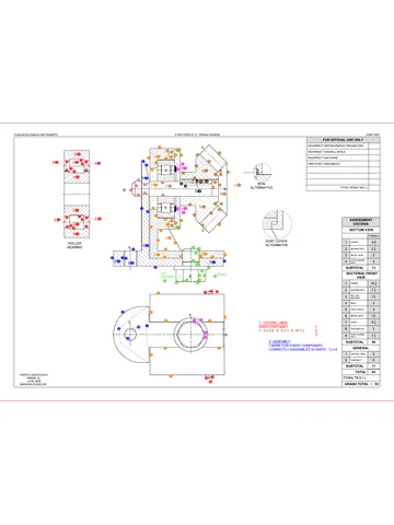
FOR OFFICIAL USE ONLY
INCORRECT SCALE
INCORRECT HATCHING
PARTS NOT ASSEMBLED
TOTAL
ASSESSMENT CRITERIA
TOP VIEW
1 |BODY 53
2 | ADJUSTING SCREW 6
3 | PLATE 1
4 |SLIDE BLOCK
5 |SPACER
6 | TOOL HOLDER
7 |M16 BOLT
SUBTOTAL
SECTIONAL FRONT VIEW
4 |BoDY 13
2 | ADJUSTING SCREW 10
3 | PLATE 3
4 | SLIDE GUIDE 33
5 | SLIDE BLOCK 43
6 |SPACER 3
7 | TOOL HOLDER 10
8 |M16 BOLT 8
SUBTOTAL] 55
GENERAL
1 | CENTRE LINES 3
2 | CUTTING PLANE 4
3 | ASSEMBLY 7
SUBTOTAL] 14
TOTAL| 88
PENALTIES (-)
GRAND TOTAL
EXAMINATION NUMBER:
EXAMINATION NUMBER [6
Copyright reserved
Study this subject
Recommended for this subject
Question paper
Engineering Graphics and Design Grade 12 P1 2016 QP (Afr)
Question paper
Engineering Graphics and Design Grade 12 P2 2023 QP (Afr)
Question paper
Engineering Graphics and Design Grade 12 P2 2023 QP (Eng)
Question paper
Engineering Graphics and Design Grade 12 P2 2022 QP (Afr)
Question paper
Engineering Graphics and Design Grade 12 P2 2019 QP (Afr)
Question paper
Engineering Graphics and Design Grade 12 P2 2015 QP (Eng)
More from Grade 12 Engineering Graphics and Design
Memorandum
Engineering Graphics and Design Grade 12 P1 2025 Memo
Memorandum
Engineering Graphics and Design Grade 12 P2 2025 Memo (Eng)
Memorandum
Engineering Graphics and Design Grade 12 P2 2025 Memo
Memorandum
Engineering Graphics and Design Grade 12 P2 2024 Memo (Eng)
Memorandum
Engineering Graphics and Design Grade 12 P1 2023 Memo (Afr)
Question paper