
basic education
Department:
« )) Basic Education
REPUBLIC OF SOUTH AFRICA
SENIOR CERTIFICATE EXAMINATIONS/
NATIONAL SENIOR CERTIFICATE EXAMINATIONS
ENGINEERING GRAPHICS AND DESIGN P1
2022
Copyright reserved
MARKS: 100
TIME: 3 hours
This question paper consists of 6 pages.
Barcode lab
DO NOT FOLD THE QUESTION PAPER IN HALF.
INSTRUCTIONS AND INFORMATION
This question paper consists of FOUR questions.
Answer ALL the questions.
ALL drawings are in first-angle orthographic projection, unless otherwise stated.
ALL drawings must be prepared using pencil and instruments, unless otherwise
stated.
ALL answers must be drawn accurately and neatly.
ALL the questions must be answered on the QUESTION PAPER, as instructed.
ALL the pages, irrespective of whether the question was attempted or not, must
be re-stapled in numerical sequence in the TOP LEFT-HAND CORNER ONLY.
8. Time management is essential in order to complete all the questions.
9. Print your examination number in the block provided on every page.
10. Any details or dimensions not given must be assumed in good proportion.
FENS
NOM
FOR OFFICIAL USE ONLY
QUESTION | MARKS OBTAINED | 3] SIGN MODERATED | 3] SIGN RE-MARKING | 3 | SIGN
1
2
3
4
TOTAL
2|0/0 2/|0/0 2/|0/0
FINAL CONVERTED MARK CHECKED BY
100
COMPLETE THE FOLLOWING:
CENTRE NUMBER
CENTRE NUMBER
EXAMINATION NUMBER
EXAMINATION NUMBER
Please tum over
Skip to contentAll 2022 papers 
View all
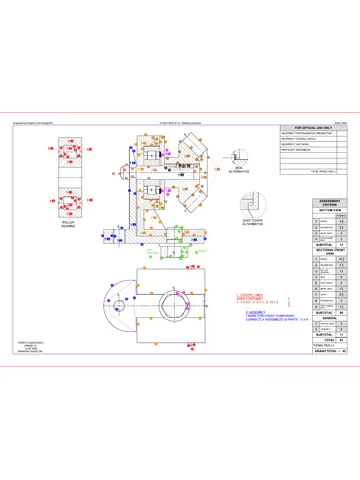
Engineering Graphics and Design Grade 12 P1 NSC June 2022 QP
Grade 12 Engineering Graphics and Design Paper 1 question paper from the NSC June Exam 2022 (English), 6 pages. Read online or download the free PDF.
Engineering Graphic And Design · Grade 12 · NSC June Exam · 2022 · English. Question paper, 6 pages. Read online or download the PDF.
- Subject
- Engineering Graphics and Design
- Grade
- Grade 12
- Language
- English
- Document type
- Question paper
- Year
- 2022
- Exam period
- NSC June Exam
- Paper
- 1
- Curriculum
- CAPS
- Pages
- 6
- File size
- 1.4 MB
Free to read online, no sign-up needed
Loading document…
Loading document…
1 of 6
This exam
NSC June Exam 2022
Document textSearch extracted text and jump to a page.
Engineering Graphics and Design/P1
>, _ | LAND SURVEYORS CERTIFICATE OF THE
Le CORNER HEIGHTS AND BOUNDARY
é LENGTHS OF STAND 108
CORNER HEIGHTS BOUNDARY
IN METRES LENGTHS IN METRES
A 21 AB 1177
B 19 Bc 13,7
c 18.8 co 15,1
D 188 DE 83
E 2 EF 88,3
F 17.3 FG 39,7
G 177 GA 102.8
22 3)
‘SYMBOL LEGEND:
4. PALM TREE
2 EVERGREEN
TREE
3. BRICK
PAVING
4, INTERNAL
FENCE
5. 2mHIGH
BOUNDARY
FENCE
6 PARKING FOR
DISABLED PEOPLE
MAIN STREET
SUB
STATION
NEW 1.5m. SIGNAGE 5,8 m MIDE
PEDESTRIAN WALL TO VEHICLE
PAVEMENT _ ENGINEER'S ENTRANCE
WITH SPECIFICATIONS
ASPHALT
FINISH SITE PLAN
SCALE 1 ; 1300
SC/NSC DBE/2022
NOTE: QUESTION 1: ANALYTICAL (CIVIL)
Contractors must verify all dimensions and
Tevals on site before commencing work. ,
Architects to be notified immediatay of any | Given:
discrepancies. The site plan of a proposed new hospital, a title panel and a table of questions. The drawing has not
been presented to the indicated scale.
AROMTECTS sMGMATURE
CUENT'S SIGNATURE Instructions:
Complete the tatle blow by neatly answering the questions, which refer to the accompanying drawing, title panel and
ANSWER 20 civil content. [30]
In the space below, draw, in neat
freehand, the SANS 10143
graphical symbol for a QUESTIONS ANSWERS
20.1 NORTH POINT
50.2 TWO-WAY SWITCH 1 | What is the reference code of the drawing? 1
2. | What scale is indicated for the site plan? 1
20.1 NORTH POINT
3, | With reference to the tile panel, what does ;
GR 20200401 - 7 refer to?
4 | What architectural frm was responsible for the design of 1
the new hospital?
What does the arrow on the sliding gate into Munchen
5 noes 1
Street indicate?
20.2 TWO-WAY SWITCH 6 | What does the abbreviation RE at 1 stand for? 1
7 | What is the height of the boundary fence in millimetres? 1
8 |Name the feature at 2 1
9 |Name the feature at 3. 1
10 | What must happen to the existing building at 4? 1
11 | What finish is required at 5? 1
12 |Name the feature at & 1
13 | What does the symbal at 7 indicate? 1
1 | 7021-0920 | FieaBteD PeOPLE | 4q | Whats the shortest distance from the proposed new A
hospital building to boundary line AB in metres?
REVISION | DATE DESCRIPTION 45 | What colour is used to represent new wood on sectional 1
elevations and floor plans?
MULLER ARCHITECTS - -
63 ALLIANZ ROAD 16 | What is the height of comer E in metres? 2
NEW GERMANY 47 | Which elevation of the proposed new hospital entrance 2
4001 ‘vqge reer faces Dortmund Avenue?
PRINTED BY DATE OF PRINT 18 |In the space below (ANSWER 18), determine the perimeter of STAND 108 in metres. 3
CREATE PRINTERS - - —
(PTY) LTD 2oe+-09-30 | [In the space below (ANSWER 19), determine the total area of the proposed new hospital building in| 5
NNGTE square metres.
SITE PLAN gq In the space provided in the title panel (ANSWER 20), draw, in neat freehand, the SANS 10143 A
<= graphical symbal for a: (20.1) NORTH POINT and (20.2) TWO-WAY SWITCH.
PROPOSED NEW HOSPITAL FOR TOTAL | 30
DR W ZULU & PARTNERS ON
STAND 108, 7 MUNCHEN STREET, ANSWER 18 £0500 ANSWER 19
SYRINGER, 4002 Show ALL calculations. Show ALL calculations.
PROJECT NUMBER: DRAWING HUMBER 8 3
3 3
CR 20200401 +7 oot=TU a proposeo |B
DATE: DRAWN: (CHECKED: ‘SCALE: NEW
2021-09-13] EINSTEIN | PLATO | 1: 1300 ° HOSPITAL [—
REFERENCE CODE 8
284039 a EXAMINATION NUMBER
15400 39100
EXAMINATION NUMBER [2
Copyright reserved
Please tum over
Engineering Graphics and Design/P1
SC/NSC
DBE/2022
QUESTION 2: SOLID GEOMETRY
Given:
© The front view and the top view of a right
regular hexagonal pyramid resting with its
base on an edge of a truncated right square
prism, The prism is centrally pierced by a right
equilateral triangular prismatic hole.
* An auxiliary view of the base of the hexagonal
pyramid
© Both solids are cut by cutting plane D-D
Instructions:
Draw, to scale 1 : 1, the following views of both
solids:
2.1 The given front view
2.2 A sectional top view on cutting plane D-D
2.3 The left view
2.4 The true shape of the cut surface of the
truncated prism
© Planning is essential
* Show ALL hidden detail.
* Show ALL construction. [40]
ASSESSMENT CRITERIA
4 |FRONT View 72
2 |SECTIONAL TOP MEW 14
3 LEFT MEW 125
4 |TRUE SHAPE 6
PENALTIES ¢)
TOTAL| 40
EXAMINATION NUMBER
EXAMINATION NUMBER [3
Copyright reserved
Please tum over
Engineering Graphics and Design/P1
SC/NSC
DBE/2022
PP.
QUESTION 3: PERSPECTIVE
Given:
Three views of a dwelling and the information
needed to draw a two-point perspective
drawing
PP - Picture plane
HL — Horizon line
GL ~ Ground line
SP = Station point
Instructions:
Complete the perspective drawing.
* Align the drawing sheet with the ground
line (GL).
* Determine and label the vanishing points.
* Show ALL construction.
* Show depth at the doors and windows.
* NO hidden detail or interior detail is required.
[38]
ASSESSMENT CRITERIA
| CONSTRUCTION 6
WALLS 113
HL
GL
ROOF 5
WINDOWS. 10
2
3
4
5
GARAGE 53
PENALTIES ¢)
TOTAL | 38
|
EXAMINATION NUMBER
EXAMINATION NUMBER: [4
Copyright reserved
Please tum over
Engineering Graphics and Design/P1 SC/NSC DBE/2022
ROOF CAP S QUESTION 4: CIVIL DRAWING
RIDGE COVER RAINWATER ITEMS
250 x 75 mm BARGE BOARD Jy Given:
150 x 100 mm GUTTER ON 2 1 Isr * The incomplete south-west elevation of a new house,
250 x 20 mm FASCIA BOARD WITH 3 all. showing the walls, the window opening, the sliding door
mm mm a > ‘
coOVE GROUND LEVEL FLOOR FINISHES 7 opening, the roof andlabels ;
7 MQTCHEN; THES. * The incomplete floor plan showing the walls, roof line,
HINISHED FLOOR LEVEL -——~ 4 2. BATHROOM: TILES positions of the doors, windows and fixtures, as well as the
| se || GROUND LEVEL 3. BEDROOM: — CARPET electrical layout
{ 4 UVING AREA: VINYL " * A schematic diagram of a section of a roof truss at cutting
‘SLIDING DOOR OPENING L, 100 plane A-A and roof notes
— © The incomplete foundation and external wall detail
FEATURES ROOM DESIGNATIONS © The built-in cupboard detail
! 61 SUDING DOOR * Room designations and floor finishes
H D2 DOOR DOOR AND WINDOW SCHEDULE * A table of rainwater items
1 W1 WINDOW « A door and window schedule
H TOHT , TORT, 50
H we Winpow F a f ctr =z 1500 A table of roof components
i { * A table of electrical symbols
Fa FIXTURES * A table of fixtures
Fl Wc TOILET The incomplete floor plan and position of the ground level of
3 WB WASH BASIN QI the new house, drawn to scale 1 : 50 and the incomplete
1 SH SHOWER § A B A i i
i S. SINK aie BS foundation and a break line for the detailed section, drawn to
' BIC BUILT-IN CUPBOARD RI scale 1 : 20, on page 6
| ELECTRICAL HITTINGS DOW wi Instructions: Answer this question on page 6.
i 4. ONE-WAY SWITCH - SINGLE-POLE wy 4.1. Using the given incomplete floor plan and ground level,
H 2. ONE-WAY SMITCH= DOUBLE-POLE 1200. draw to scale 1 : 50 the following views of the new house:
& FLUORESCENT LIGHT 1 x 40.W pe p y 4.1.1 THE COMPLETE FLOOR PLAN
4, CEILING LIGHT ——, -—, a . .
INCOMPLETE FLOOR PLAN & SMMTCHED SOCKET OUTLET ‘SLIDING DOOR (01) eI AND DOOR (02) Add the following features to the drawing:
& DISTRIBUTION BOARD = oJ 3 « ALL doors and windows
Nore: WINDOW NOTES: 3 8 fA a tla * ALL fixtures as indicated by the abbreviations
= * A= OPENING SIDE . fi i
wet aE ARROW SHOWS THE LIGHT + A= OPENING SID WINDOW (Wa) ALL electrical fittings as indicated by numbers
20 {CTION TO THE SWATCH. * ALL hatching detail
Rs \ CONNE! + ALL FRAMES = 50 mm WINDOW (wa)
) < 4.1.2 THE COMPLETE SOUTH-WEST ELEVATION
poe Kh #150 x 20 mm FIBRE CEMENT SILL UNDER ALL . aan
085 WINDOWS Show the following features on the drawing:
* _ * The outside walls, steps, window and sliding door detail
450 0d ROOF COMPONENTS ELECTRICAL SYMBOLS * ALL the roof detail, including the fascia board, barge
boards, gutters and rainwater downpipe
SCHEMATIC DIAGRAM OF A SECTION OF <== | 250x20mm FASCIA BOARD A #« fe) fe) © The finished floor level
THE ROOF TRUSS AT CUTTING PLANE AA 4.2 Using the given foundation and break line on page 6,
ROOF NOTES: a TO FIT LJ 160 x 100 mm GUTTER = draw, to scale 1 : 20, a DETAILED SECTION on cutting
‘ 80 x 200 mm. i ii i
By ROOF FITCH eee 200mm QUAL EQUAL = 75x50 am PURLINS < fo} plane A-A of the area in the ellipse shown on the
AN OBEN t incomplete floor plan.
414 x 40 mm ROOF TRUSSES Li ol | 240 250, 250 x 75 mm BARGE BOARD Show the following features on the drawing:
ON 114 x 40 mm WALL PLATES -—F 8 tt = x x The complete foundation, external wall and window
4 k 1 LL now detail
300 mm ROOF OVERHANG TO rT ROOF CAP AND RIDGE COVER: =
END OF ROOF TRUSS. g g EN ~ The roof detail, induding the fascia board, gutter and
° ZI 2 rainwater items
30 mm CORRUGATED ROOF 4 is) e ilt-it
30 mm CORRUGATED ROOF al 3 FIXTURES The steps, roof, walll and built-in cupboard detail to the
@ 1080 mm cle g aS oo 7200 right of cutting plane A-A
E 500 ey | *ALL hatching detail. ONLY the substructure may be
250 x 75 mm FIBRE CEMENT 3 Se] > hatched in neat freehand.
BARGE BOARDS ON GABLE ENDS 500 ® ° a ols ° all I
g 8 3 2
g Rg s 3| | 500 | 8
BARGE BOARDS END FLUSH WITH 50, a IcLooR g L N Label the following:
— ig:
OUTSIDE EDGE OF GUTTERS e FH 60 DOOR KNOBS EVEL * The south-west elevation
250x20mm FASCIA BOARDS GROUND | T] ssl8}o © 4 g * The floor finishes
WITH 180 x 100 mm GUTTERS al gf® 2g | Fs 3 EA * Ground level, finished floor level and damp-proof course (use
ON ALL SIDES EY il \* 3 dl * . the correct abbreviations and show them on ALL the relevant
40 mm CEILING BOARD ON 800 — nos)
40 x 40 mm BRANDERING STRIPS. WASH BASIN TOILET SHOWER SINK :
@ 450 mm cic INCOMPLETE FOUNDATION BUILT-IN CUPEGARD (we) (we) (SH) (s) ALL drawings must comply with the guidelines and graphical
AND EXTERNAL WALL DETAL
DETAIL
symbols as contained in the SANS 10143, [92]
[5
Copyright reserved
Please tum over
Engineering Graphics and Design/P1 SCINSC DBE/2022
MARK
> ¢ ALLOCATION FOR FOR OFFICIAL USE ONLY
‘gt SECTION OF ROOF | | icORRECT SCALE(S)
A USED
B NON-ALIGNMENT OF
MEWS:
c
D MEW(S) ROTATED
E SECTION VIEWED
INCORRECTLY
F
INCORRECT
S LETTERING
H
J
TOTAL TOTAL
ASSESSMENT CRITERIA
FLOOR PLAN
Posie | osrameo | sien | wovesareo
1 | Mtinbows 14
2 | Fixtures 9
y T 71 |
| y | 3 [accra | of
| 7 | 4 | HatoHINe 3
| | 5 | seis 2
| BATHROOM | SUBTOTAL 344
| | SOUTH-WEST ELEVATION
| | 1 |noor+mwor | 94
2 tees | 4d
ee | __|| | 3 [fn | 8d
Z| | 4 | vases 4
5
wl | suatora. | 234
| |
Z| | DETAILED SECTION
| \ 1 LIVING AREA | 4 | roor beta: 13
I | UAB WALL
| | 2 |ewnoows | 444
‘STEP 2
| | 4 |atc 23
| | 5 | apeis 44
|
| SUBTOTAL 34
| ToTaL] 92
| PENALTIES ¢)
——— GRAND TOTAL
FLOOR PLAN SECTION A-A EXAMINATION NUMBER
SCALE 1 : 50 SCALE 1 : 20
EXAMINATION NUMBER [6
Copyright reserved
Study this subject
Recommended for this subject
Question paper
Engineering Graphics and Design Grade 12 P1 2022 QP (Eng)
Question paper
Engineering Graphics and Design Grade 12 P1 NSC June 2021 QP
Question paper
Engineering Graphics and Design Grade 12 P1 NSC June 2021 QP
Question paper
Engineering Graphics and Design Grade 12 P1 NSC June 2018 QP
Memorandum
Engineering Graphics and Design Grade 12 P1 2022 Memo
Question paper
Engineering Graphics and Design Grade 12 P2 2022 QP (Afr)
More from Grade 12 Engineering Graphics and Design
Memorandum
Engineering Graphics and Design Grade 12 P1 2025 Memo
Memorandum
Engineering Graphics and Design Grade 12 P2 2025 Memo (Eng)
Memorandum
Engineering Graphics and Design Grade 12 P2 2025 Memo
Memorandum
Engineering Graphics and Design Grade 12 P2 2024 Memo (Eng)
Memorandum
Engineering Graphics and Design Grade 12 P1 2023 Memo (Afr)
Question paper