
basic education
Department:
« )) Basic Education
REPUBLIC OF SOUTH AFRICA
SENIOR CERTIFICATE EXAMINATION/
NATIONAL SENIOR CERTIFICATE EXAMINATION
Copyright reserved
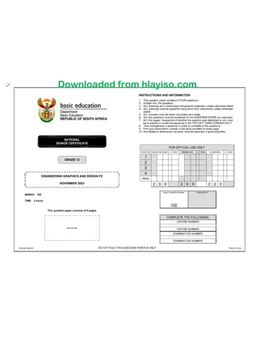
INSTRUCTIONS AND INFORMATION
FENS
PND
9.
This question paper consists of FOUR questions.
Answer ALL the questions.
ALL drawings are in third-angle orthographic projection, unless otherwise stated.
ALL drawings must be prepared using pencil and instruments, unless otherwise
stated.
ALL answers must be drawn accurately and neatly.
ALL the questions must be answered on the QUESTION PAPER, as instructed.
Do not fold any of the pages of the question paper in half.
ALL the pages, irrespective of whether the question was attempted or not, must
be re-stapled in numerical sequence in the TOP LEFT-HAND CORNER ONLY.
Time management is essential in order to complete all the questions.
10. Print your examination number in the block provided on every page.
11. Any details or dimensions not given must be assumed in good proportion.
FOR OFFICIAL USE ONLY
QUESTION | MARKS OBTAINED | 3 | SIGN MODERATED 2] SIGN RE-MARKING +| SIGN
1
ENGINEERING GRAPHICS AND DESIGN P2 2
3
2022
4
TOTAL
MARKS: 100
2/0/0 2/;0/0 2/;0/0
TIME: 3 hours
FINAL CONVERTED MARK CHECKED BY
100
This question paper consists of 6 pages.
7 CO | COMPLETE THE FOLLOWING:
| | CENTRE NUMBER
| |
| Barcode laba | CENTRE NUMBER
| | EXAMINATION NUMBER
| |
L-----~-~-~~-~~~~~~~- 4 EXAMINATION NUMBER
DO NOT FOLD THE QUESTION PAPER IN HALF. Please tum over
Skip to contentAll 2022 papers 
View all
Engineering Graphics and Design Grade 12 P2 NSC June 2022 QP
Grade 12 Engineering Graphics and Design Paper 2 question paper from the NSC June Exam 2022 (English), 6 pages. Read online or download the free PDF.
Engineering Graphic And Design · Grade 12 · NSC June Exam · 2022 · English. Question paper, 6 pages. Read online or download the PDF.
- Subject
- Engineering Graphics and Design
- Grade
- Grade 12
- Language
- English
- Document type
- Question paper
- Year
- 2022
- Exam period
- NSC June Exam
- Paper
- 2
- Curriculum
- CAPS
- Pages
- 6
- File size
- 1.2 MB
Free to read online, no sign-up needed
Loading document…
Loading document…
1 of 6
This exam
NSC June Exam 2022
Document textSearch extracted text and jump to a page.
Engineering Graphics and Design/P2
SC/NSC
DBE/2022
212
14.
QUESTION 1: ANALYTICAL (MECHANICAL)
Given:
Two sectional views of a cylinder head sub-assembly, a detailed view of a valve, a title block and a table of questions.
0220
DRAWN: vusl DATE: 02/04/2021 ALL UNSPECIFIED RADII ARE R2.
CHECKED: TARYN DATE: 03/05/2021 | TITLE CYLINDER HEAD
APPROVED: GERALD DATE: 02/07/2021 SUB-ASSEMBLY
= The drawing is not presented to the indicated scale.
+A Instructions:
oJ Complete the tate below by neatly answering the questions which refer to the accompanying drawing, the title block and
2 mechanical content. [30]
oI ol
a) L- - &}
0 ve \_ QUESTIONS ANSWERS
| — \220 ocup 1 | What is the name of the manufacturing company? 1
MACHINING 2 | Who approved the drawing? 1
| 15 OF VALVE , -
4xMS BOLTS E 3 [How many sets of drawings are there for this sub-assembly? 1
4 | On what date was the drawing prepared? 1
« VIEW 1 — g - —
55 | Referring to the projection symbol, what is the projection system -
used?
~ 6 | Which drawing program was used to prepare the drawing? 1
u 45° 7 | What size balts are required for the sub-assembly? 1
=| 2 _ 8 | How many coil springs are there in this sub-assembly? 1
n r Ra . i; 9 | Determine the complete dimensions at: A: B: Cc: D: E: 5
by 40 | What is the radius of the spherical cap? 1
r{n a 11 | What does the convention at F indicate? i
* 1 Ags > ~ WT 12 | What does the convention at G indicate? 1
—T 5.5 13 | What machining method must be used on the machined surfaces? 1
me 44 | With reference to the tdlerence, determine the minimum q
1 dimension at J.
G18
28 4g | With reference to the CAM at H, determine the displacement of the q
a4 SPHRIS follower.
! | 46 | VIEW 1 is the SECTIONAL FRONT VIEW, what is VIEW 2 q
— called?
+ ( | 17 | How many surfaces on this sub-assembly require machining? 1
L 18 |Insert the cutting plane for VIEW 1 on VIEW 2 andllabel it A-A. 34
yi 220 49 ||" the space below (ANSWER 19), draw, in neat freehand, the complete SANS 10711 conventional ,
| representation of a COIL SPRING.
NA DETAIL OF 99 | Othe drawing below (ANSWER 20), raw, in neat freehand, the complete SANS 10117 conventional | 5 5
SPECIAL M8 NUT representation for .
TOTAL | 30
) ANSWER 19 ANSWER 20
VIEW 2
MC ENGINEERING WORKS GRINDING ——>
FILE NAME: Javwi01 | DRAWING No. cami2 | PRAWNGSET: | css coz, CELL: 090 714 4922
44 DIESEL STREET
DRAWING PROGRAM: AUTOCAD 2021 SCALE 1:1 KIMBERLEY CONVENTIONAL REPRESENTATION OF
COMPLETE CONVENTIONAL
REPRESENTATION OF A COIL SPRING
DIAMOND KNURLING
EXAMINATION NUMBER
EXAMINATION NUMBER [2
Copyright reserved
Please tum over
Engineering Graphics and Design/P2
SC/NSC
DBE/2022
QUESTION 2: LOCH
NOTE: Answer QUESTIONS 2.1 and 2.2.
2.1 MECHANISM
Given:
* Asschematic drawing of a mechanism
consisting of crank OA, connecting rod BC
and swivel guide E
* The position of centre point O on the
drawing sheet
Specifications:
* The positions of centre point O and swivel
guide E are fixed.
* Connecting rod BC is pin jointed to crank
OAat A.
Motion:
Crank OA oscillates through 180° on centre
point © as connecting rod BC slides freely
through swivel guide E.
Instructions:
* Draw, to scale 1 : 1, the given schematic
drawing of the mechanism.
* Trace the loci generated by point B and by
point C for ONE oscillation of crank OA.
Show ALL construction. [20]
ASSESSMENT CRITERIA 2.1
GIVEN 4
CONSTRUCTION 2
POINTS + CURVE 14
SUBTOTAL 20
2.2 CAM
Motion:
A cam, starting at its maximum displacement
and rotating at constant velocity, imparts the
following motion to a follower:
* Itdescends 10 mm with uniform motion
over the first 60°.
* Itdescends a further 80 mm to the
minimum displacement with simple
harmonic motion over the next 90°.
© There is a dwelll period for 30°.
© Itrises 60 mm with uniform acceleration
and retardation over the next 90°.
There is a dwell period for 30°.
© Itreturns to its original position with
uniform motion over the rest of the
rotation.
Instructions:
* Draw, to a displacement scale of 1: 1 and
a rotational scale of 144 mm = 360°, the
complete displacement graph for the
required motion.
© Labdl the displacement graph and indicate
the rotational scale.
Show ALL construction. [18]
ASSESSMENT CRITERIA 2.2
1
CONSTRUCTION 6
2
POINTS + CURVE 1
3
LABELS 1
PENALTIES ¢)
2.2 SUBTOTAL 18
2.1 SUBTOTAL 20
TOTAL| 38
EXAMINATION NUMBER
EXAMINATION NUMBER
[3
Copyright reserved
Please tum over
Engineering Graphics and Design/P2 SCINSC DBE/2022
> QUESTION 3: ISOMETRIC DRAWING
° Given:
* The front view, top view and left view of a
gauge
100
* The position of point P on the drawing sheet
Instructions:
Using scale 1: 1, convert the orthographic
views of the gauge into an isometric drawing.
* Use P as the starting point for the drawing.
* Show ALL construction.
* NO hidden detail is required. 139]
139
57 25 57
ol ---
28 °
HALF OF A
7 © HEXAGON
a ©
30°
S| 3 Hy i
aqofiifi H
“ i i I &
[20 Ls Aw 28
ASSESSMENT CRITERIA
1 | PLACING + AUX EWS 4
2 | LEFT PART 17
3 | MDDLE PART 73
4 | RIGHT PART 5
‘CIRCLE + CENTRE LINES
5 | + constr’ 53
PENALTIES ¢)
TOTAL | 39
EXAMINATION NUMBER
EXAMINATION NUMBER: [4
Copyright reserved
Please tum over
Engineering Graphics and Design/P2 SC/NSC DBE/2022
224 QUESTION 4: MECHANICAL ASSEMBLY
Let 6x3
| Given:
Fase © The exploded isometric drawing of the parts of a tailstock
45° CHAMFER
10x38 Space 4B assembly, showing the position of each part relative to all
OEEP | the others
a © Orthographic views of each of the parts of the tailstock
© g| 3 3SLOTS assembly
g g EQUALLY
SPACED
ON PCD 50 _ 916 ‘Instructions:
* Answer this question on page 6.
2 8s * Draw, to scale 1: 1 and in third-angle orthographic
= _ = RS projection, the following views of the assembled parts of
g 22 | 60" the tailstock assembly:
12 30 . 4.1. A sectional front view on cutting plane A-A, as seen
from the direction of the arrow on the exploded
_t isometric drawing. The cutting plane is shown on the
oo ADJUSTING HAND WHEEL [4] right view of the tailstock (part 1).
tit al | ol 4.2. The right view
1 1 sy O86
LU —_ —| NOTE:
© Planning is essential.
a 30 © The drawing must comply with the SANS 10111
100 a guidelines.
KEY [5] © Align point P on the adjusting stud (part 3) with point P on
the tailstock (part 1).
TAILSTOCK [1] © Show THREE faces of the M16 nut (part 7) in the front
view and TWO faces of the M10 locking nut (part 9) in the
right view.
© NO hidden detail is required.
412 © Add cutting plane A-A. 193]
8 7 7 “Ty 7 M16 NUT [7]
O
216 © PARTS LIST
a4 9
~ M10 x4 PARTS. QUANTITY MATERIAL
DEAD CENTRE [2]
M10 LOCKING NUT [9] 4 ‘| TAILSTOCK 1 CASTIRON
2 |DEAD CENTRE 1 ALLOY STEEL
3 | ADJUSTING STUD 4 MILD STEEL
g 40 39 + wo Sy 4, | ADJUSTING HAND WHEEL 1 CAST STEEL
5 0
IL fm 1 @20 5 |key 1 MILD STEEL
{ 6 |WasHER 1 MILD STEEL
M16 x2/ 7 M16 NuT 1 MILD STEEL
8 |woLockine stud 1 MILD STEEL
Q |M10 LOCKING NUT 41 MILD STEEL
ADJUSTING STUD [3] TURNIT 71 SALAH ROAD
——_———_ MANE
ENGINEERING CC www.tumnitcoza
EXPLODED ISOMETRIC DRAWING TAILSTOCK ASSEMBLY
ALL DIMENSIONS ARE IN MILUIMETRES.
ALL UNSPECIFIED RADII ARE 6 mm. © & [5]
Copyright reserved
Please tum over
Engineering Graphics and Design/P2 SCINSC DBE/2022
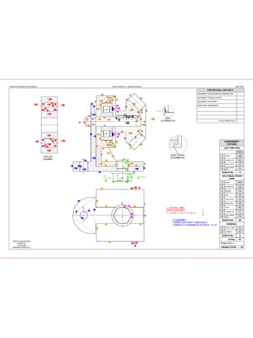
FOR OFFICIAL USE ONLY
Ce INCORRECT ORTHOGRAPHIC PROJECTION
INCORRECT OVERALL SCALE
INCORRECT HATCHING
PARTS NOT ASSEMBLED
TOTAL PENALTIES ¢)
ASSESSMENT CRITERIA
RIGHT VIEW
1 | tastock 82
2 |otsbcente™ | 8
3 | locancaur "| 64
4 | aowstine stu 13
SUBTOTAL 244
SECTIONAL FRONT VIEW
41 ‘| Taustock 14
2. | veao centre 7
3 | acwustine WHEEL 9
4 | aowustinc sruo 163
5 |inotoccnosar” | 64
6 | xe 14
SUBTOTAL 544
GENERAL
1 | cenmre unes 4
2 | curtine Lane 3
3. | assewevy 7
SUBTOTAL 14
TOTAL| 93
PENALTIES (-)
GRAND TOTAL
EXAMINATION NUMBER
EXAMINATION NUMBER [6
Copyright reserved
Study this subject
Recommended for this subject
Question paper
Engineering Graphics and Design Grade 12 P2 2022 QP (Afr)
Memorandum
Engineering Graphics and Design Grade 12 P2 2025 Memo (Eng)
Memorandum
Engineering Graphics and Design Grade 12 P2 2024 Memo (Eng)
Question paper
Engineering Graphics and Design Grade 12 P1 2022 QP (Eng)
Question paper
Engineering Graphics and Design Grade 12 P1 NSC June 2021 QP
Question paper
Engineering Graphics and Design Grade 12 P1 NSC June 2021 QP
More from Grade 12 Engineering Graphics and Design
Memorandum
Engineering Graphics and Design Grade 12 P1 2025 Memo
Memorandum
Engineering Graphics and Design Grade 12 P2 2025 Memo
Memorandum
Engineering Graphics and Design Grade 12 P1 2023 Memo (Afr)
Question paper
Engineering Graphics and Design Grade 12 P1 2023 QP (Eng)
Question paper
Engineering Graphics and Design Grade 12 P2 2023 QP (Afr)
Question paper