
Downloaded from hlayiso.com
Engineering Graphics and Design/P1
Nsc.
EC DoE/SEPTEMBER 2013
Ka ROOF HEIGHT
j &
2100
800
2835
4
CEILING HEIGHT|
3 FASCIA EIGHT 70
300 | ew ew new
POSITION inDow door |
. POSTON POSITION
Bie 205
1310 i
FLOOR HEIGHT t
oS ee
2290 SEWER LINE 140
4
NeW POSITION OF
va LAUNDRY WALL
5
1
7
LF sroreaoow 8
8
c
stantere a I I
INCOMPLETE FOUNDATION
‘AND WALL DETAIL
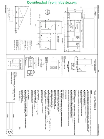
QUESTION 4: CIVIL DRAWING
SCHEMATIC ROOF TRUSS DETAIL
AAR
BR ROOF COVER PROFILE
ROOF NOTES:
ROOF COVER: 1.5 mm
IBR ON 75 x 50 PURLINS
@ 1000 cic
ROOF PITCH 24°
GANG-NAILED
TRUSSES 114 x 38
6 mm GYPSUM CEILING
BOARD ON 38 x 38
BRANDERING @ 600 mm
cic
FASCIA 208 x 32
WALL PLATE 125 x38
ny Given:
* An incomplete floor plan of the existing walls of a store room and the centre lines|
of the new walls of a proposed addition of a new laundry and toilet
© The incomplete south elevation of the changes showing the new position of the
indows, door, waste water disposal pipes, gulley and FFL.
g * The door and window schedule.
& * The incomplete roof deta
e © The incomplete foundation and wall detail
= * An electrical legend.
8 © A starting point for drawing the floor plan on answer sheet 4.
a) ahs Instructions:
Use answer sheet 4 and the information
C_ views to a scale of 1:50 according to the given specification:
m |g * The complete floor plan showing all the changes
* The complete south elevation showing all the changes
DOOR AND WINDOW * The complete sectional elevation A-A through the completed extension
SCHEDULE
DooR
3 HW FRAMED, LEDGED AND BATTENED
IRONMONGERY
'3 PAIRS of 75 mm BRASS HINGES and SCREWS
3 TWO-LEVER LOCKSETS
900 836
+O Et
2100
DOOR FRAME
2 INTERNAL,1 EXTERNAL
STANDARD HARDWOOD
%
++
af at
DOOR FRAME PROFILE
STANDARD, MERANTI
155
1835
SPECIFICATIONS:
THE FLOOR PLAN
h reference to the numbers on the floor plan the alterations are:
* Remove existing window (1) and brick up.
© Demolish wall (2), remove door and make good.
* Extend wall (3) to the new position shown.
The additions are:
* Build in new 110 mm toilet walls (4).
Build in the three new doors (5),
Build in the two new windows (6).
Add one fluorescent light (7) in the laundry and one ceiling light (7) in the toilet.
Add one switched socket (8) in the laundry.
‘Add one two pole switch (9) for the laundry and toilet.
Insert a water closet (WC), a basin (B) and a wash tub (C) as conventions
Insert the waste water disposal pipes and gulley.
Show the wall hatching.
THE SOUTH ELEVATION
Complete the south elevation showing the following:
The floor, walls and roof.
The door and window detai
The disposal pipes and gulley detai
The finished floor level.
600
THE SECTIONAL ELEVATION
Add the following features to the sectional elevation:
900
GLASS
3mm CLEAR GLASS
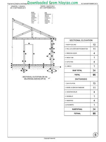
* The complete foundation, walls, floor slab, screed and roof detai
* The complete detail of the door and window.
ELECTRICAL LEGEND
ucHTs | switcHes
x
x
2x60W
SOCKET OUTLET
* ALL necessary hatching.
© Label the sectional elevation:
SECTIONAL ELEVATION A-A. [95]
NOTE:
ALL substructure hatching may be done in freehand NAME
ALL drawings must comply with the guidelines
contained in the SABS 0143. (5 )
NAME o
Copyright reserved
Skip to contentAll 2013 papers 
View all





Engineering Graphics and Design Grade 12 2013 QP
Grade 12 Engineering Graphics and Design question paper from the Eastern Cape Mock Exam 2013, 1 page. Read online or download the free PDF.
Engineering Graphic And Design · Grade 12 · Eastern Cape Mock Exam · 2013. Question paper, 1 pages. Read online or download the PDF.
- Subject
- Engineering Graphics and Design
- Grade
- Grade 12
- Document type
- Question paper
- Year
- 2013
- Exam period
- Eastern Cape Mock Exam
- Curriculum
- CAPS
- Pages
- 1
- File size
- 569.5 KB
Free to read online, no sign-up needed
Loading document…
Loading document…
1 of 1
This exam
Eastern Cape Mock Exam 2013
- Paper 1Question paper
- Paper 2Question paperMemoMemo (2)
- Other filesQuestion paperQuestion paper (2)Question paper (3)Question paper (4)Question paper (5)Question paper (6)Question paper (7)Question paper (8)Question paper (9)Question paper (10)Question paper (11)Question paper (12)Question paper (13)Question paper (14)Question paper (15)Question paper (16)Question paper (17)Question paper (18)
Document textSearch extracted text and jump to a page.
Study this subject
Recommended for this subject
Question paper
Engineering Graphics and Design Grade 12 2013 QP
Question paper
Engineering Graphics and Design Grade 12 2013 QP
Question paper
Engineering Graphics and Design Grade 12 2013 QP
Question paper
Engineering Graphics and Design Grade 12 2013 QP
Question paper
Engineering Graphics and Design Grade 12 2013 QP
Question paper
Engineering Graphics and Design Grade 12 2013 QP
More from Grade 12 Engineering Graphics and Design
Memorandum
Engineering Graphics and Design Grade 12 P1 2025 Memo
Memorandum
Engineering Graphics and Design Grade 12 P2 2025 Memo (Eng)
Memorandum
Engineering Graphics and Design Grade 12 P2 2025 Memo
Memorandum
Engineering Graphics and Design Grade 12 P2 2024 Memo (Eng)
Memorandum
Engineering Graphics and Design Grade 12 P1 2023 Memo (Afr)
Question paper