
Downloaded from hlayiso.com
INSTRUCTIONS AND INFORMATION
ISEBE LEMFUNDO LEMPUMA KOLONI
EASTERN CAPE EDUCATION DEPARTMENT
OOS-KAAP ONDERWYSDEPARTEMENT
FOR OFFICIAL USE ONLY
MODERATED
NATIONAL SENIOR CERTIFICATE MARK
1
2
3
4
GRADE 12 TOTAL
2 0 0 2 0 0
FINAL CONVERTED CHECKED BY
MARK
ENGINEERING GRAPHICS AND DESIGN P2
SEPTEMBER 2021
100
COMPLETE THE FOLLOWING:
PREPARATORY EXAMINATION
NAME
NAME
MARKS: 200
*GRDSE2* EXAMINATION CENTRE
TIME: 3 hours
This question paper consists of 6 pages.
SCHOOL
Copyright reserved
Please turn over 1
Skip to contentAll 2021 papers 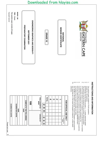
View all





Engineering Graphics and Design Grade 12 P2 2021 QP (Eng)
Grade 12 Engineering Graphics and Design Paper 2 question paper from the Eastern Cape Mock Exam 2021 (English), 6 pages. Read online or download the free PDF.
Engineering Graphic And Design · Grade 12 · Eastern Cape Mock Exam · 2021. Question paper, 6 pages. Read online or download the PDF.
- Subject
- Engineering Graphics and Design
- Grade
- Grade 12
- Document type
- Question paper
- Year
- 2021
- Exam period
- Eastern Cape Mock Exam
- Paper
- 2
- Curriculum
- CAPS
- Pages
- 6
- File size
- 787.5 KB
Free to read online, no sign-up needed
Loading document…
Loading document…
1 of 6
This exam
Eastern Cape Mock Exam 2021
Questions in this paper
Document textSearch extracted text and jump to a page.
Engineering graphics and design / P2
LE Ø36
Ø9
Downloaded from hlayiso.com NSC
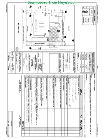
QUESTION 1: ANALYTICAL (MECHANICAL)
EC / September 2021
P
7 7
STA EXTENDED COMPRESSED
PCD 26 Given:
M16 X 1 A detailed drawing of a keyless chuck, a title block, assembled views and a table of questions. The drawings have
Ø4
3 9 not been prepared to the indicated scale.
14
Ø1 B B Instructions:
7
25 9 3 Complete the table below by neatly answering the questions, which all refer to the accompanying drawings and the
C E title block. [27]
Ø20
105
1 X 45º
Ø23 Ø12
Ø30
QUESTIONS ANSWERS
18
M34 X 2 F 1 What is the name of the company? 1
40 COIL SPRING
COLLAR 17
SCALE 2 : 1
2 In which street is the company based? 1
Ø40 B
3 Who approved the drawing? 1
D
2
Ø36 M16X1 SCALE 1 : 1 4 What is the feature at D called? 1
M34X2
1 X 45º R11 5 How many parts are used to manufacture the chuck? 1
SHAFT 3
6 How many jaws, in total, must be manufactured? 2
16 Ø10
29 12 7 What is the feature at A? 1
0°
50 15° 3 5
Ø3 8 What type of section resulted from cutting plane Z-Z? 1
3 18 6
1 X 45º
Ø4
19 30° 22 9 Name the type of section at F. 1
1 X 45º
5 15° 2
Ø22
10 What does PCD mean? 1
COMPRESSED
HEADPIECE JAW GUIDE JAW 11 Determine the measurement at E. 1
COIL SPRING
Determine the measurement at B if it needs to be
12 1
0,1 mm bigger than the shaft that penetrates it.
What was the second correction of the drawing and
13 2
was it corrected?
14 What is the feature at C? 1
15 What does the two, in M34 x 2, mean? 1
Z
16 How many turns does the coil spring have? 1
A When was the keyless chuck patented and what does
17 2
that mean?
In the space below (ANSWER 18), draw, in neat freehand, the SANS symbol for a coil
18 spring. 3
Z In the space below (ANSWER 19), draw, in neat freehand, the SANS symbol for the
19 projection system used. 4
VIEW 2 TOTAL 27
ASSEMBLY ANSWER 18 ANSWER 19
5 LEOPOLD STREET
OREGON QONCE
PARTS LIST
5600
MECHANICAL MANUFACTURES 043 604 8300
TITLE: PART MATERIAL QUANTITY
KEYLESS CHUCK
1. COLLAR STEEL 1 3.
ALL UNDIMENSIONED RADII ARE R2.
ALL DIMENSIONS ARE 2. HEADPIECE STEEL 1
SCALE: NTS 2. INSERT COIL SPRINGS AND
MILLIMETRES. HOLES ON THE ISOMETRIC 2021/04/15
3. SHAFT STEEL 1
PROGRAMME: AUTOCAD 2020 VIEW.
4. JAW STEEL 3
FILE NAME: EX127.dwg 1. THREAD NEEDS TO
2021/04/15
APPROVED: DHLABA 2021/05/15 NAME
PATENTED: 2015 5. JAW GUIDE MCS 1 BE HATCHED AT SHAFT. CHECKED: BOOYSEN 2021/04/15
QUANTITY: 300 6. COIL SPRING COPPER 3 REVISIONS DATE DRAWN: VELLUM 2020/12/15 NAME 2
Copyright reserved Please turn over
Engineering graphics and design / P2
LE
Downloaded from hlayiso.com
NSC EC / September 2021
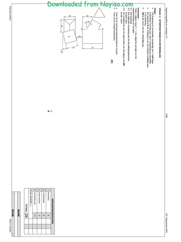
AP QUESTION 2.1: LOCI (CAM)
ST
Given:
x The bottom left 0° starting position of the displacement graph on the answer sheet for a cam.
x The specifications of the motion of the cam.
Specifications:
The cam imparts the following motion to the follower:
x The cam dwells for a period of 30°.
x It rises 60 mm with simple harmonic motion over the next 180°.
x The cam dwells for 60°.
x It returns to the original position with uniform acceleration and retardation over the rest of
the rotation.
Instructions:
x Draw, to a displacement scale of 1 : 1 and horizontal scale of 360° = 120 mm,
the complete displacement graph for the required motion.
x Label the graph and indicate the scale.
x Show ALL necessary construction. [17] ASSESSMENT CRITERIA
1 CONSTRUCTION 2
1ST DWELL +
2 SIMPLE HARMONIC 7
0°
3 2ND DWELL 1
2
4 ACCELERATION AND 621
RETARDATION
5 LABEL + SCALE 1
SUB-TOTAL 2.1 17
QUESTION 2.2: LOCI (MECHANISM)
Given:
E x Figure 1 shows the detail of a camshaft follower AB at its lowest point, connecting rod BE
C that is connected onto the camshaft follower AB as well as rotating crank CD.
x Figure 2 shows the schematic diagram of the drawing.
B
x Starting point A of the follower.
D
Motion:
x The follower reciprocates (up and down) on the vertical centre line.
x The maximum height the follower moves from point B is 40 mm.
x Follower AB moves upwards for the first 6 segments of
A the cam until it reaches the maximum height of 40 mm ASSESSMENT CRITERIA
from point B.
FIGURE 1: x The follower then moves down to the original position 1 CONSTRUCTION OF
DIAGRAM
421
for the last 6 segments of the cam.
77 x Rod BE moves as crank CD rotates clockwise around 2 CONSTRUCTION OF 6 2
fixed point D. EQUAL PARTS
38
CONSTRUCTION OF
3 LOCI 521
Instructions:
MAX. E x Draw the given schematic diagram (FIGURE 2).
x Project and draw the loci of point E to the given 4 LOCI OF POINT E 7
HEIGHT C
motion.
B 15
D x Show ALL necessary construction. [19] SUB-TOTAL 2.2 19
A
SUB-TOTAL 2.1 17
45 41
R15
TOTAL 36
A
NAME
FIGURE 2:
NAME 3
Copyright reserved Please turn over
Engineering graphics and design / P2
LE
Downloaded from hlayiso.com
NSC
QUESTION 3: ISOMETRIC
EC / September 2021
AP
ST
Given:
x Three views of a FIGURE in third angle
orthographic projection.
x Cutting plane A-A as seen in the top view.
x Starting point S.
Instructions:
x Draw, to scale 1 : 1, a sectional isometric view
of the FIGURE.
x Make point S the lowest point of the drawing.
x Show ALL necessary construction.
x NO hidden detail is required. [37]
35 20 20 35
A S 10
50
A
26
5
28
58
25 20
S S
5
110
Ø88 26
ASSESSMENT CRITERIA
1 CONSTR' + PLACEMENT 3
2 ISOMETRIC LINES 10
3 RIB 5
S 4 HEXAGON 7
5 HALF CIRCLE 321
6 SECTION + HATCHING 821
TOTAL 37
NAME
NAME 4
Copyright reserved Please turn over
Engineering graphics and design / P2
LE
Downloaded from hlayiso.com
8
NSC EC / September 2021
AP R15 3
QUESTION 4: MECHANICAL ASSEMBLY
ST
30
Given:
x The exploded isometric drawing of the parts of a gear drive
83
48 assembly, showing the position of each part relative to the
20 Ø8 Ø44
M8 6 Ø14 M8 25 others.
5
119 x Orthographic views of each of the parts of the gear drive.
□10 x Starting point S indicated on the front view of the housing and
Ø24
R5 also on the answer sheet, page 6.
Ø30 3
R5 15 15 Ø16
51
Instructions:
R5
Ø44 x Answer this question on page 6.
15
x Draw, to scale 1 : 1 and in third angle orthographic projection,
the following view of the assembled parts of the gear drive.
HANDLE (1) CRANK (2) SCREW (3) BUSH (4) x The half sectional front view of the gear drive assembly, on
cutting plane A-A, as seen from the direction of the arrow
45
shown on the exploded isometric drawing. The cutting plane is
23 shown on the right view of the housing (part 6).
A
Ø44
R45 NOTE:
4 Ø24 Ø36 100 □18 x The crank (part 2) and the crankshaft (part 12) must be drawn
53
R2 Ø2
Ø38 4 15 51 22 □10 in their vertical position as seen in the exploded isometric view.
R6 28 9 x Show, in the sectional front view, THREE faces of the M12 nut.
R4
15 R15 x Show ALL nut construction.
18 Ø46
Ø10
143 x NO hidden detail is required.
Ø18 Ø24
2 A Ø8
121 4 x All drawings must comply with the guidelines contained in
Ø30
22 Ø16 R6 Ø32 SANS 10111.
83
CIRCLIP (5) 68 Ø12 64
Add the following features on the drawing:
23 x Label the view: HALF SECTIONAL FRONT VIEW
11
S x Indicate the scale [100]
124 90
1
2 HOUSING (6) INPUT GEAR (7) SHAFT (8)
3
TITLE:
2 Ø24 GEAR DRIVE
OREGON 5 LEOPOLD STREET
Ø76
QONCE
5600
5 MECHANICAL MANUFACTURES 043 604 8300
4 Ø12
10 ALL DIMENSIONS ARE MILLIMETRES.
Ø60 Ø68
6
12 22
ALL UNSPECIFIED RADII ARE R3.
9 7 M12 NUT (9) WASHER (10) OUTPUT GEAR (11) PARTS LIST
10 PART MATERIAL QUANTITY
CONVENTIONAL METHOD: 1. HANDLE PVC 1
8 21 22 15 12
Ø18 2. CRANK CAST IRON 1
B 3. SCREW STD 1
4. BUSH COPPER 1
42
M12 5. CIRCLIP STD 1
6. HOUSING CAST IRON 1
8 7. INPUT GEAR ALUMINIUM 1
11 Ø22
61 8. SHAFT STEEL 1
FR S 145 9. M12 NUT STD 1
ON 12
TV 10. WASHER CAST IRON 1
IEW
CRANKSHAFT(12)
B 11. OUTPUT GEAR ALUMINIUM 1
12. CRANKSHAFT STEEL 1 5
Copyright reserved Please turn over
Engineering graphics and design / P2
LE
Downloaded from hlayiso.com
NSC EC / September 2021
PENALTIES
AP
ST
1 WRONG SCALE -2
2 WRONG PLACING OF VIEWS -2
3 PARTS NOT ASSEMBLED -2
4 WRONG HATCHING -2
TOTAL PENALTIES (-)
ASSESSMENT CRITERIA
HALF SECTIONAL FRONT VIEW
1 HANDLE 9
2 SCREW 921
3 CRANK 821
4 BUSH 521
5 SHAFT 12
6 CIRCLIP 221
7 INTPUT GEAR 5
8 HOUSING 1621
9 OUTPUT GEAR 4
10 CRANKSHAFT 721
11 WASHER 221
12 M12 NUT 7
13 CENTRE LINES 321
14 ASSEMBLY 6
S
15 LABEL AND SCALE 1
TOTAL 100
NAME
NAME 6
Copyright reserved
Study this subject
Recommended for this subject
Question paper
Engineering Graphics and Design Grade 12 2021 QP
Question paper
Engineering Graphics and Design Grade 12 2021 QP
Question paper
Engineering Graphics and Design Grade 12 2021 QP
Question paper
Engineering Graphics and Design Grade 12 2021 QP
Question paper
Engineering Graphics and Design Grade 12 2021 QP
Question paper
Engineering Graphics and Design Grade 12 2021 QP
More from Grade 12 Engineering Graphics and Design
Memorandum
Engineering Graphics and Design Grade 12 P1 2025 Memo
Memorandum
Engineering Graphics and Design Grade 12 P2 2025 Memo (Eng)
Memorandum
Engineering Graphics and Design Grade 12 P2 2025 Memo
Memorandum
Engineering Graphics and Design Grade 12 P2 2024 Memo (Eng)
Memorandum
Engineering Graphics and Design Grade 12 P1 2023 Memo (Afr)
Question paper