
basic education
Department:
Basic Education
REPUBLIC OF SOUTH AFRICA
NATIONAL
SENIOR CERTIFICATE
if ENGINEERING GRAPHICS AND DESIGN P2
I
lL NOVEMBER 2025 a)
MARKS: 100
TIME: 3 hours
This question paper consists of 6 pages.
| |
| |
| |
| Barcode label |
| |
| |
| |
Confidential
INSTRUCTIONS AND INFORMATION
This question paper consists of FOUR questions.
Answer ALL the questions.
ALL drawings are in third-angle orthographic projection, unless otherwise stated.
ALL drawings must be prepared using pencil and instruments, unless otherwise
stated.
ALL answers must be drawn accurately and neatly.
ALL the questions must be answered on the QUESTION PAPER, as instructed.
ALL the pages, irrespective of whether the question was attempted or not, must
be re-stapled in numerical sequence in the TOP LEFT-HAND CORNER ONLY.
8. Time management is essential in order to complete all the questions.
9. Print your examination number in the block provided on every page.
10. Any details or dimensions not given must be assumed in good proportion.
PONS
NO
FOR OFFICIAL USE ONLY
QUESTION | MARKS OBTAINED | } | SIGN MODERATED 3} SIGN RE-MARKING 3] SIGN
1
2
3
4
TOTAL
2/;0/0 2/0/0 2/;0/0
FINAL CONVERTED MARK CHECKED BY
100
COMPLETE THE FOLLOWING:
CENTRE NUMBER
CENTRE NUMBER
EXAMINATION NUMBER
Testpa Pers .co.za Testquestions .cO.Za
Skip to contentAll 2025 papers 
View all
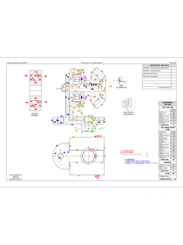
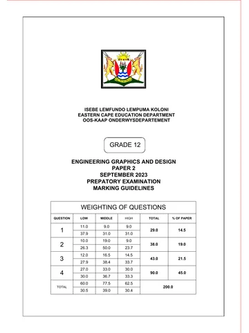
Engineering Graphics and Design Grade 12 P2 2025 QP (Eng)
Grade 12 Engineering Graphics and Design Paper 2 question paper from the NSC November Exam 2025 (English), 6 pages. Read online or download the free PDF.
Engineering Graphic And Design · Grade 12 · NSC November Exam · 2025. Question paper, 6 pages. Read online or download the PDF.
- Subject
- Engineering Graphics and Design
- Grade
- Grade 12
- Document type
- Question paper
- Year
- 2025
- Exam period
- NSC November Exam
- Paper
- 2
- Curriculum
- CAPS
- Pages
- 6
- File size
- 1.9 MB
Free to read online, no sign-up needed
Loading document…
Loading document…
1 of 6
This exam
Document textSearch extracted text and jump to a page.
Engineering Graphics and Design/P2
NSC Confidential
DBE/November 2025
QUESTION 1: ANALYTICAL (MECHANICAL)
Given:
Two views of the assembled parts of a rivet gun assembly, detailed views of the parts of the assembly, a parts list, a
title block and a table of questions. The drawings are not presented to the indicated scale.
* Instructions:
at Complete the table below by neatly answering the questions, which refer to the accompanying drawings, title block
[oio| and mechanical content. [30]
“ame QUESTIONS ANSWERS
1 | What is the file name? 1
2 | Who checked the drawing? 1
al a 3. | What is the name of the client? 1
° 4 | What program has been used to prepare the drawing? 1
} 5 | What is the website of the draughting company? 1
— 16 ina 6 | What projection system is indicated by the projection symbol? 1
= rit 7 | How many handles must be manufactured to complete the order? 4
Hy Kee 8 | If VIEW 1s the front view, what will VIEW 2 be called? 1
Lt © 9 | Name the type of section shown at A. 1
t (
= ~ a 10 | Name the type of section shown at B 1
= TOOL HEAD [4] | 11 | What does the abbreviation A/F at C stand for? 1
12 | Whatis the radius of the rounding at D? 1
| 13 | Determine the angle at E. 1
VIEW4 VIEW2 14 | Determine the complete dimensions at: F: G J 4
RIVET GUN ASSEMBLY 4g | With reference to the tolerance, determine the maximum and the | MAXIMUM 1
- minimum size of the dimension at K. MINIMUM: 1
PARTS LIST
No] PART Guanti7y | MATERIAL 16 | Calculate the height of a standard M30 nut. 1
ml sopy 7 ALUMINIUM 47 | With reference to the top machining symbol in the title block F
(QUESTION 17), what does the symbol indicate?
2. | SPRING 1 MILD STEEL Mé BOLT [5] CONNECTOR [6] { ) ul
3. | PIECE 7 MILD STEEL «| 49 | With reference to the bottom machining symbol in the title block | b: 1
Rm |e (QUESTION 18), what do the letters 'b’ and 'd' indicate? 7 1
4 | TOOL HEAD 1 MILD STEEL
5 |M6 BOLT 2 MILD STEEL > 7 49 | In the space below (ANSWER 19), complete, in neat freehand, FIGURE 19.2 as a sectional view of | 4
FIGURE 19.1 through the hole, with a SPOT FACE added to the hole.
6 | CONNECTOR 1 SPRING STEEL | oe
Pall noe 3 MLD STEEL GRP [11] _ AR aS * 90 | I" the space below (ANSWER 20), draw, to approximately the same size in neat freehand, the 5
— Wy wd SANS 10111 conventional representation of the given SPLINED SHAFT.
8 | M6 NUT 2 MILD STEEL WwW aa _
M10 }
9 | LINK 4 MILD STEEL ™ 26 / TOTAL | 30
<> THANDIE > hw STEEL PIN DIE [7] LINK [9] ANSWER 19 ANSWER 20
11 [GRIP 2 PLASTIC
FILE NAME: JJ-14213. QUANTITY: 75 RIVET GUNS
ALL UNSPECIFIED RADII | +o) cgance: 10.35 QUESTION 17:
DRAWING No. RO722 SCALE 1:2 ARE 3 mm. 0.25
COMMISSIONED BY: DRAWING ALL DIMENSIONS ARE IN
coumoooecer., — [ERANC, aurocanzoe [fugues eg _
QUESTION 18: pay !
PRO-DRAUGHTSMEN CC. www prodraw.co.za DRAWN: TOBIAS DATE: 03-07-2025 b ! | ! |
65 CHARLES ROAD, INDUSTRIA ‘ae
ROA ‘099 050 6167 CHECKED: THOMAS DATE: 23-07-2025 of 7 FIGURE 19.1 FIGURE 19.2 EXAMINATION NUMBER
THE
RIVET GUN APPROVED: KELLY DATE: 13-08-2025 d EXAMINATION NUMBER [2
Copyright reserved
Please turn over
Engineering Graphics and Design/P2
NSC Confidential
DBE/November 2025
CAMSHAFT AND FOLLOWER DETAIL,
AND MECHANISM DIAGRAM.
QUESTION 2: LOCI (CAM WITH A MECHANISM)
Given:
© The detail of a camshaft and a wedge-shaped follower at the
minimum distance from the camshaft centre
* Fixed to the given camshaft is a mechanism, consisting of
crank OA, connecting rod AB and swivel guide C, shown as a
schematic diagram
© The position of centre point © on the drawing sheet
Specifications of the cam:
« The wedge-shaped follower reciprocates along the vertical
centre line of the camshaft.
« Rotation = clockwise.
Motion of the cam:
The cam imparts the following motion to the wedge-shaped
follower:
lt rises 25 mm over the first 75° with uniform motion.
It rises a further 26 mm over the next 90° with simple harmonic
motion,
* There is a dwell period for the next 15°.
It returns to its original position with uniform motion over the
remainder of the rotation
Specifications of the mechanism:
* Connecting rod AB is pin-joined to crank OA at A.
* The position of swivel guide C is fixed.
Motion of the mechanism:
As crank OA rotates with the camshaft, connecting rod AB slides
through swivel guide C.
Instructions:
Using centre point O on the drawing sheet, draw, to scale 1: 1,
the given camshaft and wedge-shaped follower detail at the
minimum position, together with the schematic diagram of
the mechanism.
Draw, to a rotational scale of 30° = 8 mm and a displacement
scale of 1 : 1, the displacement graph for the required motion
of the cam.
Project and draw the complete cam profile from the
displacement graph.
* Show the direction of rotation of the cam profile with an arrow.
Indicate the rotational scale of the displacement graph
Trace the locus generated by point B of the mechanism for
ONE complete rotation of the camshaft
Show ALL construction and projection. [41]
ASSESSMENT CRITERIA: CAM ASSESSMENT CRITERIA: MECHANISM
GIVEN + MINIMUM 4 4
1 [oistance + ct a 1 | SIvVEN 32
2 |GRAPH CONSTRUCTION | 33 2_| CONSTRUCTION 3
PLOTTING GRAPH + Y
3. | GRAPH CURVES 6 3 | POINTS + CURVE 7
4 |CAM CONSTRUCTION 4 PENALTIES (-)
5 |PLOTTING + CAMPROFILE | 93 SUBTOTAL 134
PENALTIES (-) TOTAL| 41
SUBTOTAL 274 EXAMINATION NUMBER
EXAMINATION NUMBER [3
Copyright reserved
Please turn over
Engineering Graphics and Design/P2
NSC Confidential
DBE/November 2025
QUESTION 3: ISOMETRIC DRAWING
Given:
© The front view, top view and right view of a casting
© The position of point P on the drawing sheet
Instructions:
Using scale 1 : 1, convert the orthographic views of the casting
into an isometric drawing
* Use point P as the starting point of the drawing.
* Show ALL construction.
NO hidden detail is required [39]
36
25
r
61
25
45
16 | 24 |P
ra 20,
32 32
ASSESSMENT CRITERIA
1 |PLACING + AUX. VIEW 2
2. |FRONT PORTION 143
3 |BACK PORTION 144
4 |ciRCLes +consTR +cL| 8
PENALTIES (-)
TOTAL| 39
EXAMINATION NUMBER
EXAMINATION NUMBER [4
Copyright reserved
Please turn over
Engineering Graphics and Design/P2
NSC Confidential
DBE/November 2025
Qe 80
vs 54
138
fr PA
oo et
KEY [6] l
4x2 KEYWAY
232
4}
BALL BEARING [7]
38
135
| —3 HOLES M10
EQUISPACED
‘ON 90 PCD.
R
oy ron
yy
EXPLODED ISOMETRIC DRAWING
SHAFT [5]
a2
220,
FLANGE COUPLING [2]
BUSH [9]
228
\ 920
3 HOLES 210 CSk
TO @14 ON 90 PCD
COVER [4]
a,
&
a
g <| ees
= a) Aro
That
M10 SCREW [3]
: (M16 x2
M16 NUT [1]
44
24
| Axe KEYWAY
270
SPUR GEAR [8]
JAN EXAMPLE OF A CONVENTIONAL,
REPRESENTATION OF A SPUR
GEAR
QUESTION 4: MECHANICAL ASSEMBLY
Given:
© The exploded isometric drawing of the parts of a gearbox
assembly, showing the position of each part relative to all the
others
* Orthographic views of each of the parts of the gearbox
assembly
* An example of a conventional representation of a spur gear
Instructions:
* Answer this question on page 6
* Draw, to scale 1 : 1 and in third-angle orthographic projection,
the following views of the assembled parts of the gearbox
assembly:
4.1. A sectional front view on cutting plane A-A, as seen
from the direction of the arrow on the exploded isometric
drawing. The cutting plane is shown on the right view of
the cover (part 4).
4.2 ONLY the left half of the right view, by applying the
convention of symmetry
NOTE:
* Planning is essential.
* The drawing must comply with the SANS 10111 guidelines.
* Show THREE faces of the M16 nut (part 1) in the sectional
front view.
© Draw the ball bearing (part 7) and the spur gear (part 8) as
conventional representations in the sectional front view.
* NO hidden detail is required. [90]
PARTS LIST
PART QUANTITY MATERIAL
1 | M16 NUT 1 MILD STEEL
2. | FLANGE COUPLING 1 CAST IRON
3 | M10 SCREW 3 MILD STEEL
4 | cover 1 MILD STEEL
5 | SHAFT 1 CAST IRON
6 |key 1 MILD STEEL
7 | BALL BEARING 1 MILD STEEL
8 | SPUR GEAR 4 CAST IRON
9 | BUSH 1 BRASS
10 | HOUSING 4 CAST IRON
21 NORTH STREET
whs KLERKSDORP
DRAUGHTING www.hjc-draught.co.za
162 431 5690
GEARBOX
ALL DIMENSIONS ARE IN MILLIMETRES. © 4 [sl
Copyright reserved
Please turn over
Engineering Graphics and Design/P2 NSC Confidential DBE/November 2025
FOR OFFICIAL USE ONLY
Ce INCORRECT ORTHOGRAPHIC PROJECTION
INCORRECT OVERALL SCALE
INCORRECT HATCHING
PARTS NOT ASSEMBLED
TOTAL PENALTIES (-)
ASSESSMENT CRITERIA
RIGHT VIEW
HOUSING +
1 | symmetRY 6
COVER +
2 | screws 4
FLANGE
3 | coupuine 2
M16 NUT +
4 | shart 6
SUBTOTAL 16
SECTIONAL FRONT VIEW
4 | HOUSING 104
2 |cover 43
3 | M10 scREW 7
4 | SPUR GEAR 9
5 | BALL BEARING 23
SHAFT + KEY + 4
6 |eusn 152
FLANGE
7 | couptine 9
8 | M16 NUT 4
SUBTOTAL 62
GENERAL
1 | CENTRE LINES 3
2 | ASSEMBLY 9
SUBTOTAL 12
TOTAL | 90
PENALTIES (-)
GRAND TOTAL
EXAMINATION NUMBER
EXAMINATION NUMBER [6
Copyright reserved
Study this subject
Recommended for this subject
Question paper
Engineering Graphics and Design Grade 12 P2 2023 QP (Afr)
Question paper
Engineering Graphics and Design Grade 12 P2 2023 QP (Eng)
Question paper
Engineering Graphics and Design Grade 12 P2 2022 QP (Afr)
Question paper
Engineering Graphics and Design Grade 12 P2 2019 QP (Afr)
Question paper
Engineering Graphics and Design Grade 12 P2 2015 QP (Eng)
Question paper
Engineering Graphics and Design Grade 12 P2 2013 QP (Afr)
More from Grade 12 Engineering Graphics and Design
Memorandum
Engineering Graphics and Design Grade 12 P1 2025 Memo
Memorandum
Engineering Graphics and Design Grade 12 P2 2025 Memo (Eng)
Memorandum
Engineering Graphics and Design Grade 12 P2 2025 Memo
Memorandum
Engineering Graphics and Design Grade 12 P2 2024 Memo (Eng)
Memorandum
Engineering Graphics and Design Grade 12 P1 2023 Memo (Afr)
Question paper