
NATIONAL
SENIOR CERTIFICATE
GRADE 12
ELECTRICAL TECHNOLOGY: POWER SYSTEMS
NOVEMBER 2024
MARKING GUIDELINES
MARKS: 200
These marking guidelines consist of 16 pages.
Copyright reserved Please turn over
Skip to contentAll 2024 papers 
View all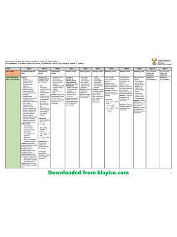
Electrical Technology Grade 12 November 2024 NSC Memo (Eng)
Grade 12 Electrical Technology memorandum from the November 2024 NSC (English), 16 pages. Read online or download the free PDF.
Electrical Technology · Grade 12 · November 2024 NSC · 2024. Memorandum. Read online or download the PDF.
- Subject
- Electrical Technology
- Grade
- Grade 12
- Document type
- Memorandum
- Year
- 2024
- Exam period
- November 2024 NSC
- Curriculum
- CAPS
- Pages
- 16
- File size
- 469.1 KB
Free to read online, no sign-up needed
Loading document…
Loading document…
1 of 16
This exam
Document textSearch extracted text and jump to a page.
Electrical Technology: Power Systems 2 DBE/November 2024
NSC – Marking Guidelines
INSTRUCTIONS TO THE MARKERS
1. All questions with multiple answers imply that any relevant, acceptable
answer should be considered.
2. Calculations:
2.1 All calculations must show the formulae.
2.2 Substitution of values must be done correctly.
2.3 All answers MUST contain the correct unit to be considered.
2.4 Alternative methods must be considered, provided that the correct
answer is obtained.
2.5 Where an incorrect answer could be carried over to the next step,
the first answer will be deemed incorrect. However, should the
incorrect answer be carried over correctly, the marker has to re-
calculate the values, using the incorrect answer from the first
calculation. If correctly used, the candidate should receive the full
marks for subsequent calculations.
3. This memorandum is only a guide with model answers. Alternative
interpretations must be considered and marked on merit. However, this
principle should be applied consistently throughout the marking session at
ALL marking centres.
Copyright reserved Please turn over
Electrical Technology: Power Systems 3 DBE/November 2024
NSC – Marking Guidelines
QUESTION 1: MULTIPLE-CHOICE QUESTIONS
1.1 B✓ (1)
1.2 A✓ (1)
1.3 B✓ (1)
1.4 A✓ (1)
1.5 C✓ (1)
1.6 B✓ (1)
1.7 D✓ (1)
1.8 D✓ (1)
1.9 C✓ (1)
1.10 B✓ (1)
1.11 D✓ (1)
1.12 A✓ (1)
1.13 B✓ (1)
1.14 D✓ (1)
1.15 C✓ (1)
[15]
Copyright reserved Please turn over
Electrical Technology: Power Systems 4 DBE/November 2024
NSC – Marking Guidelines
QUESTION 2: OCCUPATIONAL HEALTH AND SAFETY
2.1 Workplace means any premises or place where a person performs work ✓ in
the course of employment. ✓ (2)
2.2 Your right to fair labour practices. ✓
Your right to work reasonable hours. ✓
Your right to belong to a trade union.
Your right to earn a living wage.
Your right not to be discriminated against.
Your right to work in a safe environment. (2)
2.3 Poor ventilation reduces the correct amount of oxygen ✓ which might lead
to drowsiness. ✓
NOTE: If reference is made to other effects that relates to poor ventilation like
drowsiness, accidents etc. the answer will be accepted on merit. (2)
2.4 • To dismiss an employee without due process.
• To reduce the rate of remuneration without due process.
• Alter the terms of conditions of his/her employment to terms of conditions
that is less favourable to him/herself.
• Harassment and verbal abuse.
• Alter position relative to other people.
• Treat employees unfair because of race.
NOTE: If a learner only mentions an infringement of rights only 1 mark will be
awarded. Duplicate mentioning of rights will not be awarded. (2)
2.5 Equipment may be damaged making it unsafe endangering the life of other
users which might lead to an accident/injury. (2)
[10]
Copyright reserved Please turn over
Electrical Technology: Power Systems 5 DBE/November 2024
NSC – Marking Guidelines
QUESTION 3: RLC CIRCUITS
3.1 3.1.1 Inductive reactance is the opposition to the flow of current ✓ when
an inductor is connected to an ac supply. ✓
Inductive reactance is the opposition offered to the flow of
alternating current by an inductor. (2)
3.1.2 Bandwidth is the range of frequencies ✓ for which the circuit output
voltage (or) current value equals 70,7 % or more of its maximum
amplitude. ✓
NOTE: A band of frequencies centred around the resonant
frequency without mentioning 70,7% of the amplitude will be
awarded 1 mark.
The bandwidth of an RLC circuit refers to the range of frequencies
over which an RLC circuit effectively responds to an input signal
and transmits more than 50% of the power to a load. (2)
3.2 3.2.1 Lagging ✓ (1)
3.2.2 ✓
✓
✓
(3)
3.2.3
✓
✓
✓
(3)
3.2.4 ✓
✓
✓ (3)
3.2.5 VL ✓
✓
VT
(VL – VC)
θ ✓
IT VR
Rotation
VC ✓
NOTE: Rotation and VT are compulsory marks, thereafter any two
correctly placed labels.
XL and XC will not be accepted as the given diagram to complete
from the question paper indicated voltage values. (4)
Copyright reserved Please turn over
Electrical Technology: Power Systems 6 DBE/November 2024
NSC – Marking Guidelines
3.2.6 A decrease in frequency caused the inductive reactance to
decrease ✓ and the capacitive reactance to increase. ✓ When
these two values move closer to one another their effects cancel
each other out decreasing the impedance ✓ causing the current to
increase and the phase angle to decrease. (3)
3.3 3.3.1 ✓
✓
✓ (3)
3.3.2 ✓
✓
✓
(3)
3.3.3 IT = IR = 3,83 A ✓
XC = XL which indicates that the ✓
circuit is at resonance (2)
3.3.4 XC = XL ✓
✓
✓
(3)
3.3.5 ✓
✓
✓
(3)
[35]
Copyright reserved Please turn over
Electrical Technology: Power Systems 7 DBE/November 2024
NSC – Marking Guidelines
QUESTION 4: THREE-PHASE AC GENERATION
4.1 The load can be balanced in a three-phase system. ✓
Both single-phase and three-phase loads can be powered from a three-phase
system. ✓
Supply of power is constant.
A Three-phase system is more economical.
A three-phase system can be connected in star or delta. (2)
4.2 4.2.1 22 kV ✓
50 Hz ✓ (2)
4.2.2 Nuclear fuel ✓
Wind ✓
Water
Solar (2)
4.2.3 • After generation the voltage is stepped up ✓ to a value between
220 kV to 765 kV.
• It is then transmitted over long distances ✓ by means of cables
made of aluminium and steel
• to distribution stations where it is stepped down ✓ before it is
distributed further. (3)
4.3 4.3.1 Star ✓ (1)
4.3.2 R✓ Y ✓ B ✓
V
0
t
✓
120o 120o
OR
V R✓ Y✓ B✓
0 ✓ t
120o 120o
NOTE: If a candidate gives the correct sequence but in a different
order, marks will be awarded. E.g. Y, B, R or V2, V3, V1 etc. (4)
Copyright reserved Please turn over
Electrical Technology: Power Systems 8 DBE/November 2024
NSC – Marking Guidelines
4.4 4.4.1 ✓
✓
✓ (3)
4.4.2 ✓
✓ OR
✓ (3)
4.4.3 ✓
✓
✓
(3)
4.4.4 ✓
✓
✓
(3)
4.4.5 ✓
OR
✓
✓
(3)
Copyright reserved Please turn over
Electrical Technology: Power Systems 9 DBE/November 2024
NSC – Marking Guidelines
4.5 4.5.1 Synchronous motors. ✓
Phase advancers. (1)
4.5.2
L1
SUPPLY
L2
LOAD
L3
✓ ✓
C2 ✓
NOTE: Because the capacitors are not labelled in the prescribed
textbook, an exception is made to the rule of labelling. 3 Marks will
be awarded if the capacitors are correctly drawn without labels. (3)
4.5.3 The two-wattmeter method ✓ would be preferred because there is
no neutral connection available, ✓ one can only connect between
the lines. (2)
[35]
Copyright reserved Please turn over
Electrical Technology: Power Systems 10 DBE/November 2024
NSC – Marking Guidelines
QUESTION 5: THREE-PHASE TRANSFORMERS
5.1 Transformers are used for raising or lowering the voltage ✓ in an AC circuit
with a corresponding decrease or increase ✓ in current. (2)
5.2 A transformer is an electrical device that operates on the principle of
electromagnetic induction ✓ to transfer electrical energy from one electric
circuit to another without changing ✓ the frequency. (2)
5.3 5.3.1 Core-type. ✓ (1)
5.3.2 The laminated iron core reduces the circulating currents ✓ (eddy
currents) inside the core material reducing the heat ✓ generated by
them making the transformer more efficient.
The laminations are designed to increase the efficiency of a
transformer by reducing the heat generated in the core of the
transformer. (2)
5.3.3 The iron core in the core-type transformer is almost entirely
surrounded by windings ✓ whereas in the shell-type transformer
the windings are almost entirely surrounded by the iron core. ✓
Core type transformer has three limbs
Shell type transformers has five limbs (2)
5.3.4 The iron core of a transformer is continuously subjected to
magnetic polarity changes while switched on. ✓ Before the
magnetic polarity can be reversed, the residual magnetism in the
core has to be forced to zero. ✓ The power used in destroying this
residual magnetism is converted into heat. ✓ (3)
5.4 5.4.1 ✓
✓
✓
(3)
5.4.2
✓
✓
✓
(3)
Copyright reserved Please turn over
Electrical Technology: Power Systems 11 DBE/November 2024
NSC – Marking Guidelines
5.4.3
✓
OR
✓
✓
(3)
5.4.4 ✓
✓
✓
(3)
5.5 • Burnt out windings ✓ caused by excessive current which causes too much
heat dissipation.
• Electrical short circuits between the primary and secondary windings. ✓
• Windings that short circuit to the core of the transformer.
• Short circuit between adjacent windings, which change the ratios of the
transformer. (2)
5.6 5.6.1 Conservator/oil tank. ✓ (1)
5.6.2 It provides cooling. ✓
It prevents the formation of moisture on the windings. (1)
5.6.3 The Buchholz relay monitors the flow of gas in the transformer, ✓
when the gas reaches a high concentration it triggers the alarm,
and disconnects the transformer from its operation. ✓ (2)
[30]
Copyright reserved Please turn over
Electrical Technology: Power Systems 12 DBE/November 2024
NSC – Marking Guidelines
QUESTION 6: THREE-PHASE MOTORS AND STARTERS
6.1 Drill press ✓
Bench Grinder ✓
Lathe (2)
6.2 6.2.1 There is a lower than required insulation resistance reading
between coil V and earth. ✓
The insulation resistance between coil V and earth is 100 kΩ and
the minimum required insulation resistance between a coil and
earth is 1 MΩ. (1)
6.2.2 When the motor is powered any person that touches any bare
metal part of the motor may be electrocuted. ✓
Sparking may occur which might create a fire hazard.
If the motor is powered with the indicated fault, the motor can be
damaged. (1)
6.2.3
U1 V1 W1
✓ ✓ ✓
W2 U2 V2 (3)
6.3 6.3.1 ✓
✓
✓ (3)
6.3.2 ✓
✓
✓ (3)
6.3.3 %𝑠𝑙𝑖𝑝 ✓
✓
✓ (3)
OR
Copyright reserved Please turn over
Electrical Technology: Power Systems 13 DBE/November 2024
NSC – Marking Guidelines
6.4 6.4.1 MC1N/O is a retain/latching contact ✓ that will keep the contactors
energised after the start button is released. (1)
6.4.2 Contactor T is an ON-delay timer that creates a time delay ✓ of
5 seconds before switching its contacts. ✓ (2)
6.4.3 MC2 is connected in series with the normally closed contacts of the
timer and MC3. ✓ This means that it will be energised as soon as
the start button is pressed ✓ as is required by a star delta starter. (2)
6.4.4 After 5 seconds the timer T will open its N/C contact de-energising
MC2 ✓ while closing its N/O contact ✓ and energising MC3 ✓ and
in the process changing the motor coil configuration from star to
delta in the main circuit. (3)
6.5 6.5.1
✓
✓
✓ (3)
6.5.2
✓
✓
✓ (3)
6.5.3 ✓
✓
✓
✓
✓
NOTE: If a candidate substitute the phase angle, voltage and
current correct without showing the calculation of the phase
angle,
3 marks will be awarded for the substitution step.
OR
NOTE: 3 marks are allocated to the substitution step. (5)
[35]
Copyright reserved Please turn over
Electrical Technology: Power Systems 14 DBE/November 2024
NSC – Marking Guidelines
QUESTION 7: PROGRAMMABLE LOGIC CONTROLLERS (PLCs)
7.1 7.1.1 Input scan ✓
Output scan ✓ (2)
7.1.2 After the PLC has executed the programme instruction, ✓ it
processes each rung of the programme ✓ in a line-by-line
manner, sequentially. ✓ (3)
7.2 7.2.1 OR gate ✓ (1)
7.2.2
NOTE: Mark the ladder diagram according to the candidate’s
answer in 7.2.1. (3)
7.2.3 W=0✓
X=1✓
Y=1✓
Z=1✓
NOTE: Mark the truth table according to the candidate’s answer in
7.2.1. (4)
7.3 7.3.1 Discrete/Digital ✓
Analogue ✓ (2)
7.3.2 Irrigation control ✓
Monitoring of rivers and dams ✓
Numerous chemical, petrol and diesel manufacturing by remote
monitoring (2)
7.3.3 An inductive proximity sensor is used to detect the presence of
metal objects ✓ and whether they are ferrous or nonferrous. ✓
A capacitive proximity sensor uses an electrostatic field which can
sense motion, ✓ pressure, ✓ chemical composition of materials
and fluids. (4)
Copyright reserved Please turn over
Electrical Technology: Power Systems 15 DBE/November 2024
NSC – Marking Guidelines
7.4
✓ MC 1
START MC2 N/C ✓ FWD ✓
O/L STOP FWD
✓
MC1 N/O
START ✓ MC 2 ✓
MC1 N/C REV
REV ✓
✓
MC 2 N/O
NOTE: - If a candidate closes the O/L or STOP inputs that were given, a mark
will be deducted for each one that is closed, because the program will
not operate correct according to the given diagram in the question.
- If a candidate connects START REV straight to the L power rail
bypassing O/L and STOP, START REV will not be awarded a mark
because of the wrong connection of START REV
OR
M1
O/L STOP
MC1
START MC2 N/C FWD
M1 FWD
MC1 N/O
START MC2
REV MC1 N/C REV
MC2 N/O
(8)
Copyright reserved Please turn over
Electrical Technology: Power Systems 16 DBE/November 2024
NSC – Marking Guidelines
7.5 7.5.1 A = Three Phase AC supply ✓
B = AC to DC converter/Rectifier ✓
C = Filter ✓ (3)
7.5.2 AC synchronous squirrel cage induction ✓
AC asynchronous wound rotor ✓
AC synchronous with a permanent magnet
AC synchronous with brushes or brushless (2)
7.5.3 The DC to AC inverter inverts the DC voltage back to an AC
voltage. ✓ This is done by switching the IGBT's on and off ✓ at a
high frequency.✓. (3)
7.5.4 Pulse width modulation (PWM) is a modulation technique that
generates variable-width pulses ✓ to represent the amplitude of
an analogue input signal. ✓ The output switching transistor is on
more of the time for a high-amplitude signal and off more of the
time for a low-amplitude signal. ✓
OR
VSD switching frequency refers to the rate at which the DC bus
voltage is switched on and off during the pulse width modulation
(PWM) process. The on and off switching of the DC voltage is done
by Insulated Gate Bipolar Transistors (IGBTs). (3)
[40]
TOTAL: 200
Copyright reserved
Study this subject
Recommended for this subject
Question paper
Electrical Technology Grade 12 November 2024 NSC QP (Eng)
Question paper
Electrical Technology Grade 12 November 2024 NSC QP (Afr)
Question paper
Electrical Technology Grade 12 November 2024 NSC QP (Afr)
Memorandum
Electrical Technology Grade 12 Eastern Cape Prelim 2024 Memo
Question paper
Electrical Technology Grade 12 Eastern Cape Prelim 2024 QP
Question paper
Electrical Technology Grade 12 Eastern Cape Prelim 2024 QP
More from Grade 12 Electrical Technology
Annual teaching plan
Gr 12 Dig Elec ATP 2023 24
Question paper
Electrical Technology Grade 12 Gauteng June 2025 QP (Eng)
Question paper
Electrical Technology Grade 12 Eastern Cape Prelim 2024 QP
Question paper
Electrical Technology Grade 12 NSC June 2024 QP (Eng)
Question paper
Electrical Technology Grade 12 NSC June 2024 QP (Eng)
Memorandum