
Downloaded from hlayiso.com
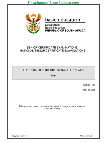
NATIONAL
SENIOR CERTIFICATE
GRADE 12
ELECTRICAL TECHNOLOGY: DIGITAL
NOVEMBER 2021
MARKS: 200
TIME: 3 hours
This question paper consists of 17 pages, a 1-page formula sheet and
a 7-page answer sheet.
Copyright reserved Please turn over
Skip to contentAll 2021 papers 
View all
Electrical Technology Grade 12 NSC November 2021 QP (Eng)
Grade 12 Electrical Technology question paper from the NSC November Exam 2021 (English), 25 pages. Read online or download the free PDF.
Electrical Technology · Grade 12 · NSC November Exam · 2021. Question paper, 25 pages. Read online or download the PDF.
- Subject
- Electrical Technology
- Grade
- Grade 12
- Document type
- Question paper
- Year
- 2021
- Exam period
- NSC November Exam
- Curriculum
- CAPS
- Pages
- 25
- File size
- 623.6 KB
Free to read online, no sign-up needed
Loading document…
Loading document…
1 of 25
This exam
Document textSearch extracted text and jump to a page.
Downloaded from hlayiso.com
Electrical Technology: Digital 2 DBE/November 2021
NSC
INSTRUCTIONS AND INFORMATION
1. This question paper consists of SIX questions.
2. Answer ALL the questions.
3. Answer the following questions on the attached ANSWER SHEETS:
QUESTIONS 3.1.6, 3.5.2 and 3.6.2
QUESTION 4.1.2
QUESTIONS 5.3.2, 5.4 and 5.5.2
QUESTION 6.8
4. Write your centre number and examination number on every ANSWER
SHEET and hand them in with your ANSWER BOOK, whether you have used
them or not.
5. Sketches and diagrams must be large, neat and FULLY LABELLED.
6. Show ALL calculations and round off answers correctly to TWO decimal
places.
7. Number the answers correctly according to the numbering system used in this
question paper.
8. You may use a non-programmable calculator.
9. Calculations must include:
9.1 Formulae and manipulations where needed
9.2 Correct replacement of values
9.3 Correct answer and relevant units where applicable
10. A formula sheet is attached at the end of this question paper.
11. Write neatly and legibly.
Copyright reserved Please turn over
Downloaded from hlayiso.com
Electrical Technology: Digital 3 DBE/November 2021
NSC
QUESTION 1: MULTIPLE-CHOICE QUESTIONS
Various options are provided as possible answers to the following questions. Choose
the answer and write only the letter (A–D) next to the question numbers (1.1 to 1.15) in
the ANSWER BOOK, e.g. 1.16 E.
1.1 Choose the correct example of an unsafe condition that is likely to cause
damage to property or an injury:
A Running in the workshop
B Spilling liquid or oil without cleaning it up
C Faulty tools or equipment
D Overloading electrical outlets when connecting many appliances (1)
1.2 An astable multivibrator generates …
A one pulse cycle of high and low when a trigger pulse is applied.
B a continuous train of pulses without the need of a trigger pulse to be
applied.
C one stable state without the trigger pulse being applied on its input.
D a sequence of triangular waveforms at the output. (1)
1.3 When applying a triangular waveform to the input of a differentiator, the output
will be …
A a DC waveform.
B an inverted triangular waveform.
C a square waveform.
D the first harmonic wave of the triangular waveform. (1)
1.4 When the input voltage to a non-inverting Schmitt trigger is smaller than the
reference voltage, the output is driven into ...
A positive saturation.
B negative saturation.
C both negative and positive saturation
D zero saturation.
1.5 When a square wave is applied to the input of an op-amp integrator circuit,
the output will be a …
A sine waveform.
B constant DC voltage.
C triangular waveform.
D square waveform.
Copyright reserved Please turn over
Downloaded from hlayiso.com
Electrical Technology: Digital 4 DBE/November 2021
NSC
1.6 Pin 1 of an integrated circuit (IC) is indicated by …
A a white '1' on the IC.
B two blue lines on the IC.
C an indent with a dot on the left of the indent.
D the pin that is red in colour. (1)
1.7 The maximum current that a 555 IC can either sink or source:
A 2A
B 200 A
C 2 mA
D 200 mA (1)
1.8 The light-altering principle that a liquid crystal display relies on is known as …
A polarisation.
B pixels.
C a matrix.
D back-lighting. (1)
1.9 A BCD decoder is a device that converts a binary code into a recognisable …
form.
A octal
B hexadecimal
C decimal
D binary (1)
1.10 Counter circuits of which the flip-flops are not triggered at the same time are
called …
A asynchronous.
B synchronous.
C pulse triggered.
D edge triggered. (1)
1.11 A register that loads the information one bit at a time and then moves the
information out of the register in the same manner for each clock pulse
applied is called the … register.
A Parallel-In: Parallel-Out
B Parallel-In: Serial-Out
C Serial-In: Parallel-Out
D Serial-In: Serial-Out (1)
Copyright reserved Please turn over
Downloaded from hlayiso.com
Electrical Technology: Digital 5 DBE/November 2021
NSC
1.12 The start-up instructions of a microcontroller is stored in the … (1)
A ROM
B RAM
C CPU
D I/O unit
1.13 A register that stores data that is needed as a part of any arithmetic operation
is known as the …
A program counter.
B memory address register.
C accumulator.
D current instruction register.
1.14 Identifying and removing errors in a program is called …
A looping.
B debugging.
C illegal data flow.
D an algorithm. (1)
1.15 One disadvantage of the inter-integrated bus (I2C) is that it …
A requires only two wires.
B is cheaper to implement.
C supports multiple master devices.
D has a slower speed. (1)
[15]
QUESTION 2: OCCUPATIONAL HEALTH AND SAFETY
2.1 State TWO functions of a health and safety representative. (2)
2.2 Give TWO examples of human rights in the workplace. (2)
2.3 Differentiate between an unsafe act and an unsafe condition. (2)
2.4 Risk analysis can be divided into different categories. Name ONE category. (1)
2.5 Define danger with reference to the Occupational Health and Safety Act, 1993
(Act 85 of 1993). (2)
2.6 Name ONE personal protective item you would use when etching a printed
circuit board (PCB). (1)
[10]
Copyright reserved Please turn over
Downloaded from hlayiso.com
Electrical Technology: Digital 6 DBE/November 2021
NSC
QUESTION 3: SWITCHING CIRCUITS
3.1 Refer to FIGURE 3.1 below and answer the questions that follow.
+9 V
R1 R2
8 4 R3
7 555 3
Bounce 6
2
Input 1 5
S LED
t C2
C1
VC1 10 nF
Y t
FIGURE 3.1: MONOSTABLE MULTIVIBRATOR
3.1.1 State the function of resistor R1. (2)
3.1.2 Write down the voltage across Pin 2 when switch S is pressed. (1)
3.1.3 State whether the LED will be ON or OFF when switch S is pressed. (1)
3.1.4 Determine the typical threshold voltage of the circuit. (1)
3.1.5 Explain why the switch bounce does not affect the output of the
circuit. (2)
3.1.6 Draw the output on the ANSWER SHEET for QUESTION 3.1.6. (3)
Copyright reserved Please turn over
Downloaded from hlayiso.com
Electrical Technology: Digital 7 DBE/November 2021
NSC
3.2 Refer to FIGURE 3.2 below and answer the questions that follow.
C1 +V
Input
Output
R2
-V
R1
R3
t1 t2 t3 t4
+V
Input
t
-V
+VSAT
Output
t
-VSAT
FIGURE 3.2: MULTIVIBRATOR
3.2.1 Identify the multivibrator circuit in FIGURE 3.2. (1)
3.2.2 State the function of resistor R2. (1)
3.2.3 Determine the polarity of the voltage on the non-inverting input
during t1. (1)
3.2.4 Explain the operation of the circuit when a positive pulse is applied to
the input. (4)
3.2.5 Explain why the output remains positive even after the pulse at t4 is
applied. (2)
Copyright reserved Please turn over
Downloaded from hlayiso.com
Electrical Technology: Digital 8 DBE/November 2021
NSC
3.3 Refer to FIGURE 3.3 below and answer the questions that follow.
+12 V
VIN
VOUT
+1 V
VIN
RF
-12 V
-1 V
+12 V
VOUT R1
-12 V
FIGURE 3.3: INVERTING SCHMITT TRIGGER
3.3.1 Identify the value of the trigger voltage levels. (2)
3.3.2 State how the trigger voltage level is determined. (1)
3.3.3 Explain whether the circuit uses open-loop or closed-loop gain. (2)
3.3.4 State TWO functions of the circuit. (2)
3.4 A summing amplifier consists of the following components:
COMPONENT DESCRIPTION
Dual supply +12 V, 0 V, -12 V
741 IC Package (DIP 8)
R1 10 kΩ
R2 10 kΩ
R3 10 kΩ
RF 100 kΩ
NOTE: R1, R2 and R3 are input resistors. RF is a feedback resistor.
3.4.1 Draw the circuit diagram. (7)
3.4.2 Calculate output voltage if the following DC voltages are applied to
the input resistors:
V1 = +0,5 V
V2 = -0,8 V
V3 = +0,2 V (3)
3.4.3 Explain how the polarity of the output will be affected if the input
voltage V3 is increased to V3 = +0,4 V. (3)
Copyright reserved Please turn over
Downloaded from hlayiso.com
Electrical Technology: Digital 9 DBE/November 2021
NSC
3.5 Refer to FIGURE 3.5 below and answer the questions that follow.
+V
R1 +9 V
VIN
741 VOUT
+V
Input VREF -9 V
R2
0
t
0V
FIGURE 3.5: COMPARATOR
3.5.1 Name the components that determine the reference voltage. (2)
3.5.2 Draw the output voltage on the ANSWER SHEET for
QUESTION 3.5.2. (3)
3.6 Refer to FIGURE 3.6 below and answer the questions that follow.
IF RF
+V
CIN +V
Input 0
t VIN -
-V IIN X VOUT
+V +
-V
0 R1
Output t
0V
-V
FIGURE 3.6: OP-AMP DIFFERENTIATOR
3.6.1 State TWO advantages of changing a passive differentiator to an
active differentiator. (2)
3.6.2 Draw the output voltage on the ANSWER SHEET for
QUESTION 3.6.2. (4)
[50]
Copyright reserved Please turn over
Downloaded from hlayiso.com
Electrical Technology: Digital 10 DBE/November 2021
NSC
QUESTION 4: SEMICONDUCTOR DEVICES
4.1 FIGURE 4.1 below shows an operational amplifier. Answer the questions that
follow.
+ V cc
3
+V +
6
Input 2
-
-V Rf
- V cc
V out
R in
FIGURE 4.1: OPERATIONAL AMPLIFIER
4.1.1 Identify the type of operational amplifier in FIGURE 4.1. (1)
4.1.2 Draw the output voltage waveform on the ANSWER SHEET for
QUESTION 4.1.2. (3)
4.1.3 Explain why operational amplifiers are known as differential voltage
amplifiers. (1)
4.1.4 Give TWO reasons why negative feedback is important when the
op amp is used as a linear amplifier. (2)
Copyright reserved Please turn over
Downloaded from hlayiso.com
Electrical Technology: Digital 11 DBE/November 2021
NSC
4.2 Refer to FIGURE 4.2 below and answer the questions that follow.
+Vcc
Ground 1 8 Supply
5 kΩ 5 kΩ 5 kΩ
Trigger 2 7 Discharge
+ _ + _
R S
Output 3 6 Threshold
Flip-
flop
Output Q Q
driver
Reset Control
4 5
voltage
FIGURE 4.2: INTERNAL LAYOUT OF 555 TIMER IC
4.2.1 Explain the function of the RS flip-flop. (2)
4.2.2 State the typical operating voltage range of the 555 IC. (2)
4.2.3 Explain the function of the three 5 kΩ resistors inside the 555 IC. (2)
4.2.4 Name TWO modes of operation for the 555 IC. (2)
4.2.5 Explain the function of the threshold input on Pin 6 of a 555 IC. (2)
4.3 Refer to FIGURE 4.3 below and explain why the output is zero volts.
+V
+V +V
0V
-V output 0 V
+V
0V
-V -V
V
FIGURE 4.3: 741 OP AMP (3)
[20]
Copyright reserved Please turn over
Downloaded from hlayiso.com
Electrical Technology: Digital 12 DBE/November 2021
NSC
QUESTION 5: DIGITAL AND SEQUENTIAL DEVICES
5.1 Explain the term common cathode with reference to the seven-segment LED
display. (2)
5.2 Draw a fully labelled circuit diagram of a sinking digital output. Indicate the
direction of current flow at the output. (5)
5.3 Refer to FIGURE 5.3 below and answer the following questions.
+5 V
R1 R2 R3
S1 X A0
S2
Y A1
S3
FIGURE 5.3: ENCODER
5.3.1 Explain the function of the encoder in FIGURE 5.3. (3)
5.3.2 Complete the logic state of inputs and outputs in boxes A to E on
the ANSWER SHEET for QUESTION 5.3.2 when S1 is pressed. (5)
Copyright reserved Please turn over
Downloaded from hlayiso.com
Electrical Technology: Digital 13 DBE/November 2021
NSC
5.4 FIGURE 5.4 below represents the logic symbol of a flip-flop.
SET
J Q
CLK
K CLR Q
FIGURE 5.4: LOGIC SYMBOLOF A FLIP-FLOP
Draw the labelled logic circuit for the logic symbol in FIGURE 5.4 using AND
gates and NOR gates only on the ANSWER SHEET for QUESTION 5.4. (9)
5.5 FIGURE 5.5 below represents the logic symbol of a half-adder. Answer the
questions that follow.
A Σ
H/A
B CO
FIGURE 5.5: LOGIC SYMBOL OF A HALF-ADDER
5.5.1 Draw the logic circuit of a half-adder using an AND gate and an
Exclusive-OR gate. (6)
5.5.2 Complete the truth table of the half-adder in the table (X, Y and Z)
on the ANSWER SHEET for QUESTION 5.5.2.
INPUTS OUTPUTS
A B Σ Co
0 0 0 0
0 1 X 0
1 0 1 Y
1 1 Z 1 (3)
5.6 Name TWO applications of counters. (2)
5.7 Explain the difference between the full-sequence counter and the truncated
counter. (2)
Copyright reserved Please turn over
Downloaded from hlayiso.com
Electrical Technology: Digital 14 DBE/November 2021
NSC
5.8 Explain the term positive edge triggering. (2)
5.9 Refer to FIGURE 5.9 below and explain the sequential operation of this
counter without the aid of a truth table.
A B C
LSB MSB
J Q0 J Q1 J Q2
K Q K Q K Q
FF0 FF1 FF2
CLK
FIGURE 5.9: THREE-BIT SYNCHRONOUS SELF-STOPPING
UP-COUNTER THAT STOPS AT 510 (1012) (8)
5.10 Draw a neatly labelled diagram of a four-bit serial-in: parallel-out shift register
using D-type flip-flops. Show ALL the inputs and outputs. (8)
[55]
Copyright reserved Please turn over
Downloaded from hlayiso.com
Electrical Technology: Digital 15 DBE/November 2021
NSC
QUESTION 6: MICROCONTROLLERS
6.1 Define a microcontroller. (3)
6.2 Explain the principle of operation of a microcontroller. (4)
6.3 Answer the following questions with reference to the RS-232 communication
protocol:
6.3.1 State the operating voltages for logic 1 and logic 0. (2)
6.3.2 Give TWO examples where the RS-232 can be used. (2)
6.4 Refer to FIGURE 6.4 below and answer the questions that follow.
Input
A B and
Output
Control bus
Y
Z
FIGURE 6.4: BLOCK DIAGRAM OF COMMUNICATION
IN A MICROCONTROLLER
6.4.1 Label the following blocks in FIGURE 6.4:
(a) A (1)
(b) B (1)
6.4.2 Identify the following bus connections:
(a) Y (1)
(b) Z (1)
6.4.3 State the purpose of the control bus. (3)
Copyright reserved Please turn over
Downloaded from hlayiso.com
Electrical Technology: Digital 16 DBE/November 2021
NSC
6.5 Refer to FIGURE 6.5 below and answer the questions that follow.
Clock
10010010 | 10010101 | 00110011
Data Data
byte byte byte
A B
Direction of data flow
FIGURE 6.5: BLOCK DIAGRAM OF SERIAL DATA SYNCHRONOUS
COMMUNICATION IN A MICROCONTROLLER
6.5.1 Label the following blocks in FIGURE 6.5:
(a) A (1)
(b) B (1)
6.5.2 Explain how data is transmitted from block A to block B in
FIGURE 6.5. (6)
6.6 Answer the following questions with reference to communication in
microcontrollers:
6.6.1 Define communication protocol in a microcontroller. (2)
6.6.2 Refer to FIGURE 6.6.2 of simplex communication below and show
the difference between simplex communication and duplex
communication by means of a neatly labelled block diagram.
TRANSMITTER RECEIVER
FIGURE 6.6.2: SIMPLEX COMMUNICATION (4)
6.6.3 Explain the difference between half-duplex communication and
full-duplex communication. (2)
6.7 Define the following terms with reference to the software of microcontrollers:
6.7.1 Program (2)
6.7.2 Flow diagram (2)
Copyright reserved Please turn over
Downloaded from hlayiso.com
Electrical Technology: Digital 17 DBE/November 2021
NSC
6.8 Design a flow diagram of a home security system with TWO sensors. The first
sensor is at the front door and the second sensor is at the window. If any of
the sensors is activated, the alarm will be activated. Once the alarm has been
reset, the sensors will continue monitoring the front door and the window. The
alarm must include a reset function. NO timing function is required.
Complete and label the flow chart of this device on the ANSWER SHEET for
QUESTION 6.8. (12)
[50]
TOTAL: 200
Copyright reserved
Downloaded from hlayiso.com
Electrical Technology: Digital DBE/November 2021
NSC
FORMULA SHEET
SEMICONDUCTOR DEVICES
VOUT RF RF
Gain A V OR AV 1
VIN R IN RIN
R
VOUT VIN F
R IN
R
VOUT VIN 1 F
R IN
SWITCHING CIRCUITS
R R R
VOUT V1 F V2 F ...VN F
R1 R2 RN
VOUT VOUT
Gain A V
VIN V1 V2 ...VN
VOUT (V1 V2 ...VN )
FLOW CHART SYMBOLS
Process
Decision
Terminator
Data
Copyright reserved
Downloaded from hlayiso.com
Electrical Technology: Digital DBE/November 2021
NSC
CENTRE NUMBER:
EXAMINATION NUMBER:
ANSWER SHEET
QUESTION 3: SWITCHING CIRCUITS
3.1.6 Bounce
Input
t
VC1
t
Output Transfer mark to
answer book
t
MOD
FIGURE 3.1.6 (3)
Copyright reserved
Downloaded from hlayiso.com
Electrical Technology: Digital DBE/November 2021
NSC
CENTRE NUMBER:
EXAMINATION NUMBER:
ANSWER SHEET
3.5.2 +V
Input
0
t
+ VSAT
Output 0
t Transfer mark to
answer book
- VSAT
MOD
FIGURE 3.5.2 (3)
3.6.2 +V
Input 0
t
-V
+V
Transfer mark to
answer book
Output 0
t
MOD
-V
FIGURE 3.6.2 (4)
Copyright reserved
Downloaded from hlayiso.com
Electrical Technology: Digital DBE/November 2021
NSC
CENTRE NUMBER:
EXAMINATION NUMBER:
ANSWER SHEET
QUESTION 4: SEMICONDUCTOR DEVICES
4.1.2
+V
Input 0
t
-V
+V
Output 0
t Transfer mark to
answer book
-V MOD
FIGURE 4.1.2 (2)
Copyright reserved
Downloaded from hlayiso.com
Electrical Technology: Digital DBE/November 2021
NSC
CENTRE NUMBER:
EXAMINATION NUMBER:
ANSWER SHEET
QUESTION 5: DIGITAL AND SEQUENTIAL DEVICES
5.3.2 +5 V
R1 R2 R3
A D
X
S1 A0
S2
B E
Y A1
S3
C
Transfer mark to
answer book
MOD
FIGURE 5.3.2 (5)
Copyright reserved
Downloaded from hlayiso.com
Electrical Technology: Digital DBE/November 2021
NSC
CENTRE NUMBER:
EXAMINATION NUMBER:
ANSWER SHEET
5.4
Transfer mark to
answer book
MOD
FIGURE 5.4 (9)
Copyright reserved
Downloaded from hlayiso.com
Electrical Technology: Digital DBE/November 2021
NSC
CENTRE NUMBER:
EXAMINATION NUMBER:
ANSWER SHEET
5.5.2
INPUTS OUTPUTS
A B Σ Co
0 0 0 0
0 1 0
1 0 1
1 1 1
Transfer mark to
answer book
MOD
TABLE 5.5.2 (3)
Copyright reserved
Downloaded from hlayiso.com
Electrical Technology: Digital DBE/November 2021
NSC
CENTRE NUMBER:
EXAMINATION NUMBER:
ANSWER SHEET
QUESTION 6: MICROCONTROLLERS
6.8
Start
Transfer mark to
answer book
MOD
FIGURE 6.8 (12)
Copyright reserved
Study this subject
Recommended for this subject
Question paper
Electrical Technology Grade 12 NSC November 2021 QP (Eng)
Question paper
Electrical Technology Grade 12 NSC November 2021 QP (Afr)
Question paper
Electrical Technology Grade 12 NSC November 2021 QP (Eng)
Question paper
Electrical Technology Grade 12 NSC June 2021 QP (Eng)
Question paper
Electrical Technology Grade 12 NSC June 2021 QP (Eng)
Question paper
Electrical Technology Grade 12 NSC November 2023 QP (Eng)
More from Grade 12 Electrical Technology
Annual teaching plan
Gr 12 Dig Elec ATP 2023 24
Memorandum
Electrical Technology Grade 12 Eastern Cape Mock 2025 Memo
Memorandum
Electrical Technology Grade 12 P1 Gauteng June 2025 Memo
Memorandum
Electrical Technology Grade 12 NSC November 2025 Memo (Afr)
Memorandum
Electrical Technology Grade 12 Eastern Cape Prelim 2024 Memo
Memorandum