
Downloaded from hlayiso.com
GRAAD 12
NATIONAL
SENIOR CERTIFICATE
GRADE 12
MECHANICAL TECHNOLOGY
FEBRUARY/MARCH 2015
MARKS: 200
TIME: 3 hours
This question paper consists of 14 pages and a 4-page formula sheet.
Copyright reserved Please turn over
Skip to contentAll 2015 papers 
View all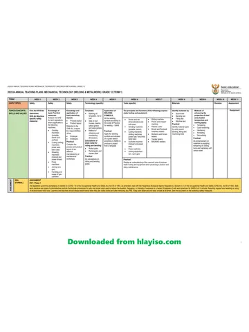
Mechanical Technology Grade 12 NSC Supplementary 2015 QP
Grade 12 Mechanical Technology question paper from the NSC Supplementary Exam 2015 (English), 18 pages. Read online or download the free PDF.
Mechanical Technology · Grade 12 · NSC Supplementary Exam · 2015. Question paper, 18 pages. Read online or download the PDF.
- Subject
- Mechanical Technology
- Grade
- Grade 12
- Document type
- Question paper
- Year
- 2015
- Exam period
- NSC Supplementary Exam
- Curriculum
- CAPS
- Pages
- 18
- File size
- 610.8 KB
Free to read online, no sign-up needed
Loading document…
Loading document…
1 of 18
This exam
NSC Supplementary Exam 2015
Document textSearch extracted text and jump to a page.
Downloaded from hlayiso.com
Mechanical Technology 2 DBE/Feb.–Mar. 2015
NSC
INSTRUCTIONS AND INFORMATION
1. Write your centre number and examination number in the spaces provided on
the ANSWER BOOK.
2. Read ALL the questions carefully.
3. Answer ALL the questions.
4. Number the answers correctly according to the numbering system used in this
question paper.
5. Start EACH question on a NEW page.
6. Show ALL calculations and units. Round off final answers to TWO decimal
places.
7. You may use a non-programmable/scientific calculator and drawing/
mathematical instruments.
8. The value of gravitational force should be taken as 10 m/s2.
9. All dimensions are in millimetres, unless stated otherwise in the question.
10. Write neatly and legibly.
11. A formula sheet appears at the end of the question paper.
12. Use the criteria below to assist you in managing your time.
QUESTION CONTENT MARKS TIME
1 Multiple-choice questions 20 15 minutes
2 Safety 10 10 minutes
3 Tools and Equipment 12 10 minutes
4 Materials 13 10 minutes
5 Terminology 30 20 minutes
6 Joining Methods 25 25 minutes
7 Forces 30 30 minutes
8 Maintenance 15 15 minutes
9 Systems and Control 25 25 minutes
10 Turbines 20 20 minutes
TOTAL 200 180 minutes
Copyright reserved Please turn over
Downloaded from hlayiso.com
Mechanical Technology 3 DBE/Feb.–Mar. 2015
NSC
QUESTION 1: MULTIPLE-CHOICE QUESTIONS
Various options are given as possible answers to the following questions. Choose the
answer and write only the letter (A–D) next to the question number (1.1–1.20) in the
ANSWER BOOK, for example 1.21 A.
1.1 What safety precaution is applicable to the MIGS/MAGS welding process?
A Always use a striker to light the torch and not a match or lighter.
B The welder is completely insulated by means of boots and gloves.
C Open the cylinder valves quickly.
D Allow for oxygen and acetylene leaks. (1)
1.2 Which hardness tester uses a steel ball to determine the hardness of steel?
A Vickers tester
B Rockwell tester
C Victor tester
D Brinell tester (1)
1.3 The gas analyser is used during the fuel mixture setting of a motor-car
engine. Which ONE of the following is the CORRECT reason for a high
carbon-monoxide reading?
A Low compression
B Worn valves
C A clogged air filter
D Worn piston rings (1)
1.4 The function of the tensile tester:
A To determine the compressive stress and ultimate pushing stress on a
piece of a material
B To demonstrate a pulling stress on a supported beam
C To demonstrate the deflection of a simply supported beam
D To determine yield stress, ultimate pulling stress and percentage of
elongation on a piece of material (1)
1.5 When carbon steel is heated at a uniform rate, the temperature rises evenly
to 700 °C. The temperature then remains constant for a while. This point is
known as the … point.
A decalescent
B melting
C lower critical
D heating (1)
Copyright reserved Please turn over
Downloaded from hlayiso.com
Mechanical Technology 4 DBE/Feb.–Mar. 2015
NSC
1.6 Steel can be hardened and annealed at a temperature between
885 °C and 925 °C. What percentage carbon content will allow for this
hardening and annealing? Use the iron carbon equilibrium diagram in
FIGURE 1.1 below.
1 000
AC3
900 AC3
800
Temperature – °C
720 AC1 AC1
700
600
0 0,2 0,4 0,6 0,8 1,0 1,2 1,4
% – Carbon content
FIGURE 1.1
A 0,60%
B 0,20%
C 0,80%
D 0,40% (1)
1.7 Name the tool that is used to set the cutting tool perpendicular to the axis of
the work piece when cutting a screw thread on the lathe:
A Screw-pitch gauge
B Screw-thread ring gauge
C Centre gauge
D Screw gauge (1)
1.8 What is the standard ratio of a taper key?
A 1 in 50
B 1 in 100
C 1 in 150
D 1 in 75 (1)
Copyright reserved Please turn over
Downloaded from hlayiso.com
Mechanical Technology 5 DBE/Feb.–Mar. 2015
NSC
1.9 What defect appears as a groove in the parent metal, directly along the
edges of the weld?
A Undercutting
B Slag inclusion
C Porosity
D Incomplete penetration (1)
1.10 Which ONE of the following is an example of a destructive test?
A X-ray test
B Liquid dye penetration test
C Ultrasonic test
D Bend test (1)
1.11 Compressive stress can be defined as an internal force in material that
provides resistance against a … load.
A shearing
B tensile
C compressive
D linear (1)
1.12 Which ONE of the following statements describes Pascal's law?
A The area is inversely proportional to the pressure on it if the
temperature remains constant.
B The pressure exerted on the surface of the liquid in a closed hydraulic
system is transmitted equally in all directions.
C The pressure is proportional to the volume if the temperature remains
constant.
D The volume is inversely proportional to the pressure on it if the
temperature increases. (1)
1.13 The following statement describes an advantage of a belt-drive system
compared to a gear-drive system:
A Stronger
B Needs no lubrication
C Changes direction
D More durable (1)
Copyright reserved Please turn over
Downloaded from hlayiso.com
Mechanical Technology 6 DBE/Feb.–Mar. 2015
NSC
1.14 Calculate the strain when a tensile force causes a stress of 6 MPa in a work
piece. The material has an elasticity module of 3 GPa:
A 2 x 10³
B 500
C 1,8 x 10⁹
D 2 x 10⁻³ (1)
1.15 What is the composition of cutting fluid?
A Soluble oil and water
B Grease and water
C Engine oil and water
D Machine oil and water (1)
1.16 What does the abbreviation ECU stand for in terms of the vehicle
management system?
A Economical control unit
B Electronic control unit
C Electricity control unit
D Engine control unit (1)
1.17 How is the supercharger driven?
A Hydraulically driven
B Gas driven
C Pneumatically driven
D Mechanically driven (1)
1.18 During a gas turbine application the auxiliary power unit is described
as … gas turbine designed for auxiliary power.
A a large
B a medium
C a larger
D a small (1)
1.19 Force is a vector unit which is recognised by …
A magnitude only.
B direction only.
C magnitude and direction.
D volume and direction. (1)
Copyright reserved Please turn over
Downloaded from hlayiso.com
Mechanical Technology 7 DBE/Feb.–Mar. 2015
NSC
1.20 What does point D denote in FIGURE 1.2 below?
D
AB C
STRESS
E
STRAIN
FIGURE 1.2
A Limit of proportionality
B Maximum strain
C Maximum stress
D Limit of elasticity (1)
[20]
Copyright reserved Please turn over
Downloaded from hlayiso.com
Mechanical Technology 8 DBE/Feb.–Mar. 2015
NSC
QUESTION 2: SAFETY
2.1 All personal and environmental safety rules have already been taken care
of when a surface grinder is used. State THREE safety rules which are only
applicable while the surface grinder is being used. (3)
2.2 Give TWO reasons why the pressure gauge of a hydraulic press must be
tested regularly. (2)
2.3 Why is it important to keep the copper tips of the spot welder constantly
cool during use? (1)
2.4 Describe the position of the following regarding the cylinder leakage test:
2.4.1 Stroke (1)
2.4.2 Piston (1)
2.4.3 Valves (1)
2.5 At what angle to the bearing should a bearing puller be used? (1)
[10]
QUESTION 3: TOOLS AND EQUIPMENT
3.1 Explain how a voltmeter and an ammeter are connected to a circuit. (2)
3.2 Describe the purpose of the following tests:
3.2.1 Beam-bending test (2)
3.2.2 Cylinder-leakage test (2)
3.3 When Johnny conducted a dry compression test, the test indicated that the
first cylinder had a very low reading. After conducting a wet test, the reading
was higher. To what conclusion can Johnny come about the test? (2)
3.4 FIGURE 3.1 below shows a compression tester that is used to check the
compression of a cylinder. Label parts A–D.
A
B
C
D
FIGURE 3.1 (4)
[12]
Copyright reserved Please turn over
Downloaded from hlayiso.com
Mechanical Technology 9 DBE/Feb.–Mar. 2015
NSC
QUESTION 4: MATERIALS
4.1 Name TWO characteristics of each of the following microscopic structures
of steel:
4.1.1 Ferrite (2)
4.1.2 Pearlite (2)
4.2 Determine the microscopic structure that best describes the compound of
iron and carbon (iron carbide) by analysing steel and cast iron. (2)
4.3 The table below indicates the carbon content, typical uses, heat treatment
and properties of steel. Write your answers for QUESTIONS 4.3.1, 4.3.2
and 4.3.3 in the ANSWER BOOK.
CARBON HEAT
TYPICAL USES PROPERTIES
CONTENT TREATMENT
Low
4.3.1 Annealing Strong; durable
0,1–0,25%
Medium Crankshafts; pliers; Tough; hard
4.3.2
0,25–0,55% screwdrivers surface
High Cutting tools;
Hardening 4.3.3
0,55–1,00% springs; hammers (3)
4.4 Define the terms below with reference to the iron-carbon equilibrium diagram:
4.4.1 Lower critical point (AC 1 ) (2)
4.4.2 Critical temperature (2)
[13]
QUESTION 5: TERMINOLOGY
5.1 Explain step by step how a metric V-screw thread with a pitch of 1,5 mm is
cut on the centre lathe. (11)
5.2 Calculate the cutting depth of a metric V-screw thread with a pitch of
2,5 mm using the compound slide method. (3)
5.3 Calculate the simple indexing needed to cut a gear with 82 teeth. (3)
5.4 The length of a parallel key is 102 mm. Calculate:
5.4.1 The diameter of the shaft (3)
5.4.2 The width of the key (3)
5.4.3 The thickness of the key (3)
5.5 Show, by means of neat labelled sketches, the difference between upcut
milling and downcut milling. (4)
[30]
Copyright reserved Please turn over
Downloaded from hlayiso.com
Mechanical Technology 10 DBE/Feb.–Mar. 2015
NSC
QUESTION 6: JOINING METHODS
6.1 FIGURE 6.1 shows a welding machine with different attachments.
FIGURE 6.1
6.1.1 Identify the welding machine in FIGURE 6.1. (1)
6.1.2 Label parts A–G in FIGURE 6.1. (7)
6.2 Explain the operating principle of the X-ray testing equipment as applicable
to a welded joint. (6)
6.3 State THREE advantages of metal-arc shielded welding (MIGS/MAGS). (3)
6.4 What is the purpose of a bend test? (2)
6.5 State TWO causes of the following welding defects:
6.5.1 Incomplete penetration (2)
6.5.2 Welding craters (2)
6.6 Which TWO aspects regarding welding techniques should be kept in mind
during arc welding? (2)
[25]
Copyright reserved Please turn over
Downloaded from hlayiso.com
Mechanical Technology 11 DBE/Feb.–Mar. 2015
NSC
QUESTION 7: FORCES
7.1 Four forces of 150 N, 210 N, 250 N and 360 N respectively, as shown in
FIGURE 7.1 below, act on the same point. Calculate the magnitude and
direction of the equilibrant for this system of forces.
250 N
210 N
110°
45°
360 N
150 N
FIGURE 7.1 (15)
7.2 A square steel bar with 100 mm x 100 mm sides is subjected to a
compressive force of 80 kN. Determine, by means of calculations, the
stress in the material. (5)
7.3 Define Hooke's law. (3)
7.4 FIGURE 7.2 below shows a uniform beam that is supported by two vertical
supports, A and B. Two vertical point loads are exerted onto the beam, as
well as a uniformly distributed load of 50 N/m, over the total left half of the
beam.
Determine, by means of calculations, the magnitudes of the reactions in
supports A and B.
50 N/m uniformly 400 N 600 N
distributed load
1,5 m 5m 2m 4,5 m
A B
FIGURE 7.2 (7)
[30]
Copyright reserved Please turn over
Downloaded from hlayiso.com
Mechanical Technology 12 DBE/Feb.–Mar. 2015
NSC
QUESTION 8: MAINTENANCE
8.1 State TWO advantages of a cutting fluid. (2)
8.2 Define preventive maintenance. (1)
8.3 Car manufacturers recommend that the timing chain of a car engine be
replaced every 90 000 km. Answer the questions that follow.
8.3.1 Give TWO reasons why a chain drive is preferred to a belt drive. (2)
8.3.2 Give TWO reasons why a stretched chain has to be replaced. (2)
8.3.3 Explain in point form how you would remove and replace the
timing chain of an engine. (6)
8.4 Why is it desirable for engine oil to have a high flash point? (2)
[15]
QUESTION 9: SYSTEMS AND CONTROL
9.1 FIGURE 9.1 below shows a gear system used to control a hoisting machine.
The driver gear has 50 teeth and rotates at 660 r/min. The idler gear that is
used to change the direction, rotates at 1 000 r/min. The driven gear has
60 teeth.
Gear C
Gear A
Gear B
Idler gear
Driver gear
Driven gear
FIGURE 9.1
Determine by means of calculations:
9.1.1 The number of teeth on the idler gear (3)
9.1.2 The rotation frequency of the driven gear in revolutions per
second (3)
Copyright reserved Please turn over
Downloaded from hlayiso.com
Mechanical Technology 13 DBE/Feb.–Mar. 2015
NSC
9.2 The drive pulley of a belt-drive system rotates at 1 640 r/min. The drive
pulley has a diameter of 175 mm and the driven pulley a diameter of 80 mm.
The belt thickness is 12 mm.
Take the belt thickness into consideration and determine, by means of
calculations:
9.2.1 The rotation frequency of the driven pulley in revolutions per
second (3)
9.2.2 The belt speed of the system (3)
9.3 A hydraulic system is used to compress scrap metal for recycling. The
specifications of the system are presented diagrammatically in FIGURE 9.2.
Ø 38 mm Ø 150 mm
240 N
Load = ? N
Piston A
Piston B
FIGURE 9.2
Determine, by means of calculations:
9.3.1 The fluid pressure in the hydraulic system while in equilibrium (3)
9.3.2 The force exerted by piston B (4)
9.4 Describe the purpose of the vehicle-engine management system. (4)
9.5 Describe the purpose of the anti-lock brake system (ABS). (2)
[25]
Copyright reserved Please turn over
Downloaded from hlayiso.com
Mechanical Technology 14 DBE/Feb.–Mar. 2015
NSC
QUESTION 10: TURBINES
10.1 State TWO positive impacts a water turbine will have on the environment
and society. (2)
10.2 Define the following terms regarding a water turbine:
10.2.1 Specific speed (2)
10.2.2 Free load speed/Runaway speed (2)
10.3 State the function of a steam turbine. (2)
10.4 Name THREE types of steam turbines. (3)
10.5 What is the advantage of using gas turbines on naval vessels? (2)
10.6 Define turbo boost. (2)
10.7 Explain in point form the operation of a twin-screw supercharger. (5)
[20]
TOTAL: 200
Copyright reserved
Downloaded from hlayiso.com
Mechanical Technology 1 DBE/Feb.–Mar. 2015
NSC
FORMULA SHEET FOR MECHANICAL TECHNOLOGY – GRADE 12
1. BELT DRIVES
πDN
1.1 Belt speed =
60
π ( D + t )× N
1.2 Belt speed = (t = belt thickness)
60
1.3 Belt mass = area × length × density (A = thickness × width)
diameter of driven pulley
1.4 Speed ratio =
diameter of driver pulley
1.5 N 1 D1 = N 2 D2
π( D + d ) ( D − d ) 2
1.6 Open - belt length = + + 2c
2 4c
π( D + d ) ( D + d )2
1.7 Crossed -belt length = + + 2c
2 4c
2π NT
1.8 Power ( P ) =
60
T1
1.9 Ratio of tight side to slack side =
T2
(T1 − T2 ) π D N
1.10 Power (P) = where T1 = force in the tight side
60
T2 = force in the slack side
T1 − T2 = effective force (Te )
T1
1.11 Width =
permissible tensile force
2. FRICTION CLUTCHES
2.1 Torque ( T ) = µWnR
where µ = coefficient of friction
W = total force
n = number of friction surfaces
R = effective radius
2 π NT
2.2 Power ( P ) =
60
Copyright reserved Please turn over
Downloaded from hlayiso.com
Mechanical Technology 2 DBE/Feb.–Mar. 2015
NSC
3. STRESS AND STRAIN
force F
3.1 Stress = or ( σ = )
area A
change in length ( ΔL )
3.2 Strain ( ε ) =
original length ( L )
stress σ
3.3 Young' s mod ulus ( E ) = or ( )
strain ε
3.4 πD 2 π (D 2 − d 2 )
Area round bar = and Area round tube =
4 4
Area square bar = L2 and Area sqaure tube = L2 − l 2
4. HYDRAULICS
force ( F )
4.1 Pressure ( P ) =
area ( A )
4.2 Volume = cross-sectional area × stroke length ( l or s )
4.3 Work done = force × distance
πD 2
4.4 Area =
4
F1 F2
4.5 =
A1 A2
5. GEAR DRIVES
2π NT
5.1 Power ( P ) =
60
product of the number of teeth on driven gears
5.2 Gear ratio =
product of the number of teeth on driving gears
N input product of the number of teeth on driven gears
5.3 =
N output product of the number of teeth on driving gears
5.4 Torque = force × radius
5.5 Torque transmitted = gear ratio × input torque
Copyright reserved Please turn over
Downloaded from hlayiso.com
Mechanical Technology 3 DBE/Feb.–Mar. 2015
NSC
pitch-circle diameter ( PCD )
5.6 Module ( m ) =
number of teeth ( T )
5.7 N 1T1 = N 2T2
circular pitch ( CP ) × number of teeth ( T )
5.8 Pitch-circle diameter ( PCD ) =
π
5.9 Outside diameter ( OD ) = PCD + 2 module
5.10 Addendum ( a ) = module ( m )
5.11 Dedendum ( b ) = 1,157 m or Dedendum ( b ) = 1,25 m
5.12 Cutting depth ( h ) = 2,157 m or Cutting depth ( h ) = 2,25 m
5.13 Clearance ( c ) = 0,157 m or Clearance ( c ) = 0,25 m
5.14 Circular pitch ( CP ) = m × π
6. PULLEY DRIVES
6.1 N 1 D1 = N 2 D2
2 π NT
6.2 Power ( P ) =
60
diameter of driven pulley
6.3 Velocity Ratio =
diameter of driver pulley
7. KEYWAYS
diameter of shaft
7.1 Width of key =
4
diameter of shaft
7.2 Thickness of key =
6
7.3 Length of the key = 1,5 × diameter of shaft
7.4 Taper of key = 1 : 100
Copyright reserved Please turn over
Downloaded from hlayiso.com
Mechanical Technology 4 DBE/Feb.–Mar. 2015
NSC
8. LEVERS
load ( W )
8.1 Mechanical advantage ( MA ) =
effort ( F )
8.2 Input movement ( IM ) = effort × distance moved by effort
8.3 Output movement ( OM ) = load × distance moved by load
input movement
8.4 Velocity ratio ( VR ) =
output movement
9. SCREW THREADS
9.1 Pitch diameter = outside diameter − ½ pitch
9.2 Pitch circumference = π × pitch diameter
9.3 Lead = pitch × number of starts
9.4 Height of screw thread = 0,866 × pitch ( P )
9.5 Depth of screw thread = 0,613 × pitch ( P )
height
9.6 Number of turns =
lead
10. INDEXING
CINCINNATI DIVIDING HEAD TABLE FOR HOLE CIRCLES IN PLATE
Hole circles
Side 1 24 25 28 30 34 37 38 39 41 42 43
Side 2 46 47 49 51 53 54 57 58 59 62 66
40
Indexing =
n
Copyright reserved
Study this subject
Recommended for this subject
Question paper
Mechanical Technology Grade 12 NSC Supplementary 2015 QP
Question paper
Mechanical Technology Grade 12 Eastern Cape Mock 2015 QP
Question paper
Mechanical Technology Grade 12 Eastern Cape Mock 2015 QP
Question paper
Mechanical Technology Grade 12 NSC November 2015 QP (Afr)
Question paper
Mechanical Technology Grade 12 NSC November 2015 QP (Eng)
Question paper
Mechanical Technology Grade 12 NSC Supplementary 2018 QP
More from Grade 12 Mechanical Technology
Annual teaching plan
Gr 12 Weld Met ATP 2023 24
Memorandum
Mechanical Technology Grade 12 Eastern Cape Prelim 2024 Memo
Memorandum
Mechanical Technology Grade 12 Eastern Cape Prelim 2024 Memo
Memorandum
Mechanical Technology Grade 12 Eastern Cape Prelim 2024 Memo
Memorandum
Mechanical Technology Grade 12 Eastern Cape Prelim 2024 Memo
Memorandum