
Downloaded from hlayiso.com
NATIONAL
SENIOR CERTIFICATE
GRADE 12
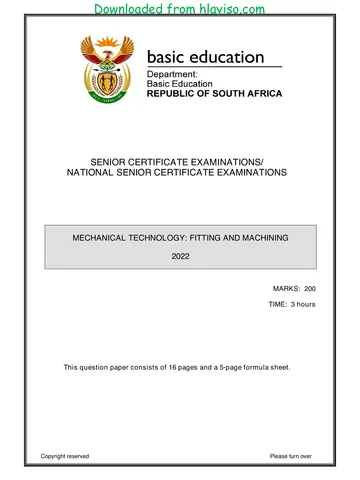
MECHANICAL TECHNOLOGY: FITTING AND MACHINING
NOVEMBER 2022
MARKS: 200
TIME: 3 hours
This question paper consists of 16 pages and a 6-page formula sheet.
Copyright reserved Please turn over
Skip to contentAll 2022 papers 
View all
Mechanical Technology Grade 12 NSC November 2022 QP (Eng)
Grade 12 Mechanical Technology question paper from the NSC November Exam 2022 (English), 22 pages. Read online or download the free PDF.
Mechanical Technology · Grade 12 · NSC November Exam · 2022. Question paper, 22 pages. Read online or download the PDF.
- Subject
- Mechanical Technology
- Grade
- Grade 12
- Document type
- Question paper
- Year
- 2022
- Exam period
- NSC November Exam
- Curriculum
- CAPS
- Pages
- 22
- File size
- 756.2 KB
Free to read online, no sign-up needed
Loading document…
Loading document…
1 of 22
This exam
Document textSearch extracted text and jump to a page.
Downloaded from hlayiso.com
Mechanical Technology: Fitting and Machining 2 DBE/November 2022
NSC
INSTRUCTIONS AND INFORMATION
1. Write your centre number and examination number in the spaces provided on
the ANSWER BOOK.
2. Read ALL the questions carefully.
3. Answer ALL the questions.
4. Number the answers correctly according to the numbering system used in this
question paper.
5. Start EACH question on a NEW page.
6. Show ALL calculations and units. Round off final answers to TWO decimal
places.
7. Candidates may use non-programmable scientific calculators and drawing
instruments.
8. The value of gravitational acceleration should be taken as 10 m/s 2.
9. All dimensions are in millimetres, unless stated otherwise in the question.
10. Write neatly and legibly.
11. A formula sheet is attached at the end of the question paper.
12. Use the criteria below to assist you in managing your time.
TIME
QUESTION CONTENT MARKS
IN MINUTES
GENERIC
1 Multiple-choice Questions 6 6
2 Safety 10 10
3 Materials 14 14
SPECIFIC
4 Multiple-choice Questions 14 10
5 Terminology (Lathe and Milling Machine) 18 20
6 Terminology (Indexing) 28 25
7 Tools and Equipment 13 10
8 Forces 33 33
9 Maintenance 18 12
10 Joining Methods 18 12
11 Systems and Control (Drive Systems) 28 28
TOTAL 200 180
Copyright reserved Please turn over
Downloaded from hlayiso.com
Mechanical Technology: Fitting and Machining 3 DBE/November 2022
NSC
QUESTION 1: MULTIPLE-CHOICE QUESTIONS (GENERIC)
Various options are provided as possible answers to the following questions. Choose
the answer and write only the letter (A–D) next to the question numbers
(1.1 to 1.6) in the ANSWER BOOK, e.g. 1.7 E.
1.1 Which ONE of the following is the last stage when applying first aid?
A Examination
B Treatment
C Diagnosis
D Transport (1)
1.2 What is the maximum thickness of sheet metal that a manual guillotine can
cut?
A 0,2 mm
B 1,2 mm
C 2,2 mm
D 3,2 mm (1)
1.3 Which part of a hydraulic press is used to safely keep the platform at a
desired height?
A Return spring
B Plunger
C Supporting pin
D Base (1)
1.4 Which ONE of the following tests is used to determine resistance to
penetration?
A File test
B Machining test
C Hardness test
D Sound test (1)
1.5 Which machine is used to conduct a spark test on carbon steels?
A Bench grinder
B Drilling machine
C Lathe
D Milling machine (1)
1.6 Which ONE of the following materials will have a high ringing sound when
tapped with a hammer during a sound test?
A Cast iron
B Cast steel
C Mild steel
D Aluminium (1)
[6]
Copyright reserved Please turn over
Downloaded from hlayiso.com
Mechanical Technology: Fitting and Machining 4 DBE/November 2022
NSC
QUESTION 2: SAFETY (GENERIC)
2.1 Name TWO vital functions of an injured person that must be checked when
first aid is applied. (2)
2.2 Give a reason why safety goggles must be worn when working with an angle
grinder. (1)
2.3 Name TWO types of safety guards that are used where the opening at the
guillotine shears is greater than 10 mm. (2)
2.4 State THREE safety precautions that must be adhered to before gas welding
is undertaken. (3)
2.5 State TWO disadvantages of the product layout of machines. (2)
[10]
QUESTION 3: MATERIALS (GENERIC)
3.1 State THREE properties that can be obtained from heat-treatment processes. (3)
3.2 Describe the following heat-treatment processes:
3.2.1 Tempering (4)
3.2.2 Hardening (3)
3.3 Give TWO examples of case-hardened products used in the industry. (2)
3.4 Why is steel cooled in still air, away from a draught, during the normalising
process? (2)
[14]
Copyright reserved Please turn over
Downloaded from hlayiso.com
Mechanical Technology: Fitting and Machining 5 DBE/November 2022
NSC
QUESTION 4: MULTIPLE-CHOICE QUESTIONS (SPECIFIC)
Various options are provided as possible answers to the following questions. Choose
the answer and write only the letter (A–D) next to the question numbers
(4.1 to 4.14) in the ANSWER BOOK, e.g. 4.15 E.
4.1 Identify the lathe component in FIGURE 4.1 below.
FIGURE 4.1
A Cross slide
B Revolving centre
C Compound slide
D Chuck (1)
4.2 What is the purpose of a centre gauge?
A To set the cutting tool square to the axis
B To assist with centre drilling
C To check if the screw thread has been cut accurately
D To assist in counting the number of cutting tools needed (1)
4.3 A CNC (computer numerical control) machine ...
A counts the number of work pieces cut.
B is fed with figures and letters (data input).
C can only be operated manually.
D can switch on by itself. (1)
4.4 From where is absolute motion measured during CNC milling?
A The last position of the cutting tool
B The middle of the work piece
C The beginning of the work piece
D A common point (1)
Copyright reserved Please turn over
Downloaded from hlayiso.com
Mechanical Technology: Fitting and Machining 6 DBE/November 2022
NSC
4.5 Which hardness tester uses a diamond cone to indent material?
A Moment hardness tester
B Force hardness tester
C Rockwell hardness tester
D Brinell hardness tester (1)
4.6 Identify the type of micrometer in FIGURE 4.6 below.
FIGURE 4.6
A Screw-thread micrometer
B Inside micrometer
C Outside micrometer
D Depth micrometer (1)
4.7 Which ONE of the following is the definition of load?
A The internal resistance in a body
B The external force acting upon matter
C The quantity of matter a body contains
D The internal force present in material (1)
Copyright reserved Please turn over
Downloaded from hlayiso.com
Mechanical Technology: Fitting and Machining 7 DBE/November 2022
NSC
4.8 Identify R in the stress-strain diagram in FIGURE 4.8 below.
S
Q R
P T
FIGURE 4.8
A Stress point
B Yield point
C Elastic limit
D Maximum stress (1)
4.9 Which ONE of the following is manufactured from bakelite?
A Roof sheeting
B Water pipe
C Distributor rotor
D Shopping bag (1)
4.10 Which ONE of the following is an advantage of Vesconite?
A Very versatile
B Low load-bearing strength
C Low chemical resistance
D Poor machinability (1)
4.11 Which diameter on the screw thread bears the maximum load?
A Major diameter
B Pitch diameter
C Root diameter
D Crest diameter (1)
Copyright reserved Please turn over
Downloaded from hlayiso.com
Mechanical Technology: Fitting and Machining 8 DBE/November 2022
NSC
4.12 The sides of the cutting tool used to cut a square screw thread should be
ground at an angle ...
A conforming to the helix angle of the screw thread.
B smaller than the helix angle.
C bigger than the helix angle.
D square to the square screw thread. (1)
4.13 Which ONE of the following is an example of a pulley system?
A Engine horn
B Scissors car jack
C Car brake system
D Block and tackle (1)
4.14 How is the fluid in a hydraulic system kept clean?
A Raise the temperature of the fluid in the system.
B Constantly top up the fluid in the system.
C Insert a check valve in the system.
D Insert a filter in the system. (1)
[14]
QUESTION 5: TERMINOLOGY (LATHE AND MILLING MACHINE) (SPECIFIC)
5.1 State TWO advantages of cutting a taper on a lathe by using the tailstock
set-over method. (2)
5.2 FIGURE 5.2 below shows a taper with an included angle of 8° which should
be cut on a lathe by using the compound slide method. Calculate the diameter
(D) of the taper.
290
D 42 8°
FIGURE 5.2 (4)
Copyright reserved Please turn over
Downloaded from hlayiso.com
Mechanical Technology: Fitting and Machining 9 DBE/November 2022
NSC
5.3 Calculate the following dimensions for a parallel key suitable for a 65 mm
diameter shaft:
5.3.1 Width (2)
5.3.2 Thickness (2)
5.3.3 Length (2)
5.4 State ONE disadvantage of straddle milling. (1)
5.5 Name TWO types of milling processes that can be done by using vertical
milling. (2)
5.6 A 12 mm milling cutter must be centred on a 60 mm diameter work piece by
using the steel ruler method on a milling machine as shown in FIGURE 5.6
below. Calculate X in order to centre the milling cutter.
X
FIGURE 5.6 (3)
[18]
Copyright reserved Please turn over
Downloaded from hlayiso.com
Mechanical Technology: Fitting and Machining 10 DBE/November 2022
NSC
QUESTION 6: TERMINOLOGY (INDEXING) (SPECIFIC)
6.1 A spur gear, with a pitch-circle diameter of 165 mm and 110 teeth, is needed
for a gearbox.
Calculate the following:
6.1.1 Module (2)
6.1.2 Outside diameter (2)
6.2 FIGURE 6.2 below shows an external dovetail that must be manufactured for
a compound slide of a centre lathe.
y 120 y
D E
h = 30
60° 60°
B
11
.2.
4
12 11
A C
x 11 m 11 x
W
FIGURE 6.2
Calculate the following:
6.2.1 Maximum width (W) of the dovetail (6)
6.2.2 Distance (m) between the precision rollers (6)
6.3 A spur gear with 163 teeth has to be manufactured for a hoist crane.
The dividing head has a ratio of 40 : 1.
HINT: A = 160 divisions for the simple indexing
6.3.1 Calculate the indexing that is needed. (3)
6.3.2 Calculate the change gears that are required. (5)
6.4 Name TWO types of balancing methods. (2)
6.5 State TWO advantages of balancing the rotating components of a machine. (2)
[28]
Copyright reserved Please turn over
Downloaded from hlayiso.com
Mechanical Technology: Fitting and Machining 11 DBE/November 2022
NSC
QUESTION 7: TOOLS AND EQUIPMENT (SPECIFIC)
7.1 Describe the function of a screw-thread micrometer. (2)
7.2 The Brinell hardness tester is used to determine the hardness of metal. Use a
neat labelled drawing to demonstrate how the test is performed. (4)
7.3 Name TWO types of forces that can act on a body. (2)
7.4 FIGURE 7.4 below shows a metric screw thread. Answer the questions that
follow.
A
B C
FIGURE 7.4
7.4.1 Label A–C. (3)
7.4.2 Calculate the pitch diameter of an M12 x 1,75 screw thread. (2)
[13]
Copyright reserved Please turn over
Downloaded from hlayiso.com
Mechanical Technology: Fitting and Machining 12 DBE/November 2022
NSC
QUESTION 8: FORCES (SPECIFIC)
8.1 FIGURE 8.1 below shows a system of four forces acting on the same point.
Answer the questions that follow.
HINT: Draw and complete the diagram for the forces shown in FIGURE 8.1.
Show ALL the horizontal and vertical components before doing the
calculations.
25 N
40 N
70°
60°
120 N
55 N
FIGURE 8.1
Calculate the following:
8.1.1 The sum of the horizontal components (4)
8.1.2 The sum of the vertical components (4)
8.1.3 The magnitude of the resultant (2)
8.1.4 The angle and direction of the resultant (3)
Copyright reserved Please turn over
Downloaded from hlayiso.com
Mechanical Technology: Fitting and Machining 13 DBE/November 2022
NSC
8.2 FIGURE 8.2 below shows a uniform beam supported by two vertical supports,
A and B. Two point loads and a uniformly distributed load (UDL) are exerted
onto the beam.
75 N 55 N
1,5 m 3,5 m 7m
UDL 12 N/m
14 m
A B
FIGURE 8.2
Calculate the following:
8.2.1 The uniformly distributed load on the beam (1)
8.2.2 The magnitude of the reaction force at A (5)
8.2.3 The magnitude of the reaction force at B (5)
8.3 A compressive force of 85 kN, that causes a stress of 36 MPa, is exerted onto
a round tube. The original length of the tube is 120 mm.
Calculate the following:
8.3.1 The resistance area (3)
8.3.2 The change in length, in millimetres, caused by the force if Young's
modulus for this material is 90 GPa (6)
[33]
QUESTION 9: MAINTENANCE (SPECIFIC)
9.1 Name THREE important consequences of failing to conduct preventative
maintenance in an engineering workshop. (3)
9.2 State THREE different types of mechanical drive systems. (3)
9.3 Name the element used to enhance the strength of glass fibre. (1)
Copyright reserved Please turn over
Downloaded from hlayiso.com
Mechanical Technology: Fitting and Machining 14 DBE/November 2022
NSC
9.4 State TWO properties of EACH of the following products:
9.4.1 Bakelite (2)
9.4.2 Carbon fibre (2)
9.5 Name ONE natural substance that is used to manufacture PVC. (1)
9.6 Name THREE ways of conducting preventative maintenance on mechanical
equipment. (3)
9.7 Name the TWO main types of plastic composites. (2)
9.8 Which plastic composite is used for non-stick coatings on frying pans? (1)
[18]
QUESTION 10: JOINING METHODS (SPECIFIC)
10.1 Explain the following terms as applicable to screw thread terminology:
10.1.1 Lead (4)
10.1.2 Helix angle (2)
10.2 A two-start square threaded bar needs to be manufactured. The lead of the
square thread is 42 mm and the crest diameter is 90 mm. The clearance
angle on the cutting tool must be 3°.
Calculate the following:
10.2.1 Pitch (3)
10.2.2 Pitch diameter (2)
10.2.3 Helix angle of the thread (3)
10.2.4 Leading angle (2)
10.2.5 Following angle (2)
[18]
Copyright reserved Please turn over
Downloaded from hlayiso.com
Mechanical Technology: Fitting and Machining 15 DBE/November 2022
NSC
QUESTION 11: SYSTEMS AND CONTROL (DRIVE SYSTEMS) (SPECIFIC)
11.1 FIGURE 11.1 below shows a hydraulic lift. The lift needs to raise a maximum
load of 34 000 N at the ram with a diameter of 250 mm. The force applied on
the plunger is 215 N. Answer the questions that follow.
34 000 N
215 N
PLUNGER
d=?
RAM
D = 250 mm
FLUID
FIGURE 11.1
Calculate the following:
11.1.1 The fluid pressure in the hydraulic system in MPa (4)
11.1.2 The diameter of the plunger in mm (5)
11.2 Name TWO types of hydraulic filters. (2)
11.3 Identify the hydraulic symbols in FIGURES 11.3.1 and 11.3.2 below.
11.3.1
i
FIGURE 11.3.1 (1)
11.3.2
i
FIGURE 11.3.2 (1)
Copyright reserved Please turn over
Downloaded from hlayiso.com
Mechanical Technology: Fitting and Machining 16 DBE/November 2022
NSC
11.4 A belt pulley with a diameter of 0,15 m is mounted on the shaft of a petrol
engine that drives a fuel pump. The engine rotates at 1 330 r/min. A pulley
with a diameter of 0,32 m is fitted to the fuel pump. The tensile force of the
belt in the tight side is 175 N and the force in the slack side is 130 N.
Calculate the following:
11.4.1 The rotational frequency in r/s of the driven pulley on the fuel pump (3)
11.4.2 The power transmitted in watt (4)
11.5 FIGURE 11.5 below shows a gear drive system. The number of teeth for
each gear is shown in the diagram. Driver gear A is fixed on the input shaft.
The rotational frequency of the output shaft is 625 r/min. Answer the
questions that follow.
TA = 20 TB = 40
TC = 35 TD = 50
TE = 25 TF = 80
NA =? r/min
NF = 625 r/min
FIGURE 11.5
11.5.1 Identify the type of gear drive system shown in FIGURE 11.5. (1)
11.5.2 Calculate the rotational frequency of the input shaft. (4)
11.6 During a machining test on a lathe, it was found that the tangential force on
the cutting tool was 250 N. The diameter of the work piece was 50 mm.
Calculate the torque on the lathe spindle. (3)
[28]
TOTAL: 200
Copyright reserved
Downloaded from hlayiso.com
Mechanical Technology: Fitting and Machining 1 DBE/November 2022
NSC
FORMULA SHEET FOR MECHANICAL TECHNOLOGY:
FITTING AND MACHINING
1. BELT DRIVES
1.1 Belt speed = πDN
60
1.2 Belt speed = π D t N (t = belt thickness)
60
1.3 Belt mass = Area × Length × Density (A = thickness × width)
Diameter of driven pulley
1.4 Speed ratio =
Diameter of driver pulley
1.5 Belt length (flat) = [(D + d) × 1,57] + (2 × centre distance)
π D d D d
2
1.6 Open-belt length = 2c
2 4c
π D d D d
2
1.7 Crossed-belt length = 2c
2 4c
1.8 Power (P) =
T1 T2 π D N
60
Where:
T1 = force in the tight side
T2 = force in the slack side
T1 – T2 = effective tensile force (Te)
T1
1.9 Ratio between tight side and slack side =
T2
T1
1.10 Width =
Permissible tensile force
1.11 NDR × DDR = NDN × DDN
Copyright reserved Please turn over
Downloaded from hlayiso.com
Mechanical Technology: Fitting and Machining 2 DBE/November 2022
NSC
2. STRESS AND STRAIN
Ashaft = π d
2
2.1
4
Apipe = π D d
2 2
2.2
4
Maximum stress/Break stress
2.3 Safety factor =
Safe working stress
F
2.4 Stress = Force OR σ
Area A
Change in length ΔL
2.5 Strain = OR ε
Original length oL
Stress σ
2.6 Young's modulus = OR E
Strain ε
3. HYDRAULICS
3.1 Pressure = Force OR P
F
Area A
3.2 Volume = Area × Stroke length (l or s)
3.3 Work done = Force × distance
3.4 PA = PB
FA F
3.5 B
AA AB
4. GEAR DRIVES
4.1 Power (P) = 2π NT
60
Product of teeth on driven gear Ninput
4.2 Gear Ratio = OR Speed ratio =
Product of teeth on driver gear Noutput
Copyright reserved Please turn over
Downloaded from hlayiso.com
Mechanical Technology: Fitting and Machining 3 DBE/November 2022
NSC
Ninput Product of teeth on driven gear
4.3 =
Noutput Product of teeth on driver gear
4.4 NA × T A = NB × T B
4.5 Torque = Force × Radius
4.6 Torque transmitted = Gear ratio × Input torque
Pitch-circle diameter PCD
4.7 Module = OR m=
Number of teeth T
Circular pitch × Number of teeth
4.8 Pitch-circle diameter =
π
OR
PCD = CPT
4.9 Outside diameter (OD) = PCD + 2(m)
4.10 Addendum = Module OR a=m
4.11 Dedendum (b) = 1,157 × m OR Dedendum (b) = 1,25 × m
4.12 Cutting depth (h) = 2,157 × m OR Cutting depth (h) = 2,25 × m
4.13 Clearance (c) = 0,157 × m OR Clearance (c) = 0,25 × m
4.14 Circular pitch (CP) = m × π
4.15 Working depth (WD) = 2 × m OR Working depth (WD) = 2 × a
5. PULLEYS
5.1 NDR × DDR = NDN × DDN
5.2 Power (P) = 2π NT
60
Diameter of driven pulley
5.3 Velocity ratio =
Diameter of driver pulley
Copyright reserved Please turn over
Downloaded from hlayiso.com
Mechanical Technology: Fitting and Machining 4 DBE/November 2022
NSC
6. KEYWAYS
6.1 Width (W) = D
4
6.2 Thickness (T) = D
6
6.3 Length (L) = 1,5 × D
Where:
D = Diameter of shaft
6.4 Standard taper for taper key: 1 in 100 or 1 : 100
7. CINCINNATI DIVIDING HEAD TABLE FOR MILLING MACHINE
Hole circles
Side 1 24 25 28 30 34 37 38 39 41 42 43
Side 2 46 47 49 51 53 54 57 58 59 62 66
Change gears
Gears 24 x 2 28 32 40 44 48 56 64 72 86 100
7.1 Indexing = 40 (n = number of divisions)
n
A n 40
A n
Dr Dr 40
7.2 OR
Dn A 1 Dn A
Where:
A = chosen number of divisions
n = real number of divisions
8. DOVETAILS
Where:
R = Radius of precision roller
y = Distance from top edge of dovetail in relation to bottom corner of dovetail
x = Distance from middle of precision roller to bottom corner of dovetail
θ = Dovetail included angle (normally 60°)
h = Height of dovetail
w = Minimum width of dovetail
W = Maximum width of dovetail
m = Distance between rollers
M = Distance over rollers
Copyright reserved Please turn over
Downloaded from hlayiso.com
Mechanical Technology: Fitting and Machining 5 DBE/November 2022
NSC
9. TAPERS
θ D-d
9.1 tan = (l = Taper length)
2 2l
L D - d
9.2 Tail stock set - over = (L = Distance between centres)
2l
10. SCREW THREADS
10.1 Mean diameter = Outside diameter – (½ × Pitch) OR Dm = OD ‒ P
2
10.2 Effective diameter (Deff) = Pitch diameter (Dp) = Mean diameter (Dm)
10.3 Lead = Pitch × Number of starts
10.4 Height of screw thread = 0,866 × Pitch (P)
10.5 Depth of screw thread = 0,613 × Pitch (P)
10.6 Helix angle: Tan θ = Lead
π Dm
10.7 Leading angle = 90° ‒ (Helix angle + Clearance angle)
10.8 Following angle = 90° + (Helix angle ‒ Clearance angle)
10.9 DP = DN – (0,866 × P)
Copyright reserved Please turn over
Downloaded from hlayiso.com
Mechanical Technology: Fitting and Machining 6 DBE/November 2022
NSC
11. PYTHAGORAS' THEOREM AND TRIGONOMETRY
r
y
x
y
11.1 Sin θ
r
x
11.2 Cos θ
r
y
11.3 Tan θ
x
11.4 r 2 x2 y2
Copyright reserved
Study this subject
Recommended for this subject
Question paper
Mechanical Technology Grade 12 NSC November 2022 QP (Afr)
Question paper
Mechanical Technology Grade 12 NSC November 2022 QP (Afr)
Question paper
Mechanical Technology Grade 12 NSC November 2022 QP (Afr)
Question paper
Mechanical Technology Grade 12 NSC June 2022 QP (Eng)
Question paper
Mechanical Technology Grade 12 NSC June 2022 QP (Afr)
Question paper
Mechanical Technology Grade 12 NSC November 2023 QP (Afr)
More from Grade 12 Mechanical Technology
Annual teaching plan
Gr 12 Weld Met ATP 2023 24
Memorandum
Mechanical Technology Grade 12 Eastern Cape Prelim 2024 Memo
Memorandum
Mechanical Technology Grade 12 Eastern Cape Prelim 2024 Memo
Memorandum
Mechanical Technology Grade 12 Eastern Cape Prelim 2024 Memo
Memorandum
Mechanical Technology Grade 12 November 2024 NSC Memo (Eng)
Memorandum