
Downloaded from hlayiso.com
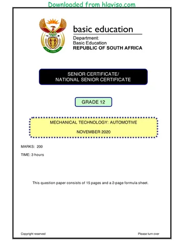
SENIOR CERTIFICATE/
NATIONAL SENIOR CERTIFICATE
GRADE 12
MECHANICAL TECHNOLOGY: AUTOMOTIVE
NOVEMBER 2020
MARKING GUIDELINE
MARKS: 200
These marking guideline consist of 19 pages.
Copyright reserved Please turn over
Skip to contentAll 2020 papers 
View all
Mechanical Technology Grade 12 NSC November 2020 Memo (Eng)
Grade 12 Mechanical Technology memorandum from the NSC November Exam 2020 (English), 19 pages. Read online or download the free PDF.
Mechanical Technology · Grade 12 · NSC November Exam · 2020. Memorandum, 19 pages. Read online or download the PDF.
- Subject
- Mechanical Technology
- Grade
- Grade 12
- Document type
- Memorandum
- Year
- 2020
- Exam period
- NSC November Exam
- Curriculum
- CAPS
- Pages
- 19
- File size
- 400.7 KB
Free to read online, no sign-up needed
Loading document…
Loading document…
1 of 19
This exam
Document textSearch extracted text and jump to a page.
Downloaded from hlayiso.com
Mechanical Technology (Automotive) 2 DBE/November 2020
SC/NSC – Marking Guidelines
QUESTION 1: MULTIPLE-CHOICE QUESTIONS (GENERIC)
1.1 A (1)
1.2 D (1)
1.3 A (1)
1.4 C (1)
1.5 B (1)
1.6 B (1)
[6]
Copyright reserved Please turn over
Downloaded from hlayiso.com
Mechanical Technology (Automotive) 3 DBE/November 2020
SC/NSC – Marking Guidelines
QUESTION 2: SAFETY (GENERIC)
2.1 Work procedures on machine:
Switch off machine. (1)
2.2 The horizontal band saw:
No adjustments to machine or work piece.
Ensure sufficient coolant on work piece and blade.
Do not leave machine unattended while in operation.
Do not lean on machine.
Keep hands clear from blade.
(Any 2 x 1) (2)
2.3 Surgical gloves:
Prevent contamination of wound
To prevent transmission of HIV/AIDS or any blood related diseases to
the first aid helper. (2)
2.4 Personal protective equipment (PPE) during arc welding:
Welding helmet / Helmet
Safety goggles / Face shield
Leather apron / Apron
Leather gloves / Gloves
Leather spat / Spats
Safety boots / Safety shoes
Over-all
Skull cap
Neck protection
Ear plugs / Ear muffs.
Respirator
(Any 2 x 1) (2)
2.5 Responsibility of the employer regarding the health and safety:
Sufficient lighting
Sufficient ventilation
Provide first-aid equipment
Provide a safe / clean working environment
Provide personal protective equipment (PPE)
Provide safety training to employees
(Any 1 x 2) (2)
2.6 Responsible for administering first aid:
A qualified / trained first aid person (1)
[10]
Copyright reserved Please turn over
Downloaded from hlayiso.com
Mechanical Technology (Automotive) 4 DBE/November 2020
SC/NSC – Marking Guidelines
QUESTION 3: MATERIALS (GENERIC)
3.1 Tests to identify various metals:
3.1.1 Sound test:
Tapping the metal with a hammer (any metal object) and
identify the sound.
Dropping the metal on the floor and identify the sound.
(Any 1 x 2) (2)
3.1.2 File test:
File the metal and pay attention to the bite of the file into the
metal. The bigger the bite the softer the metal. OR The
smaller the bite the harder the metal. (2)
3.2 Purpose of heat treatment of steel:
To change the properties of steel.
To change the grain structure of steel.
(Any 1 x 2) (2)
3.3 Purpose of case hardening on steel:
To create a hard / wear resistance surface / case with a tough core. (2)
3.4 The tempering process for steel:
Heat the steel to a temperature (temper colour) below the critical
temperature.
Soak it at that temperature for a period.
Quench / cool in an appropriate quenching agent. (water, brine, or oil) (3)
3.5 THREE factors for heat treatment of steel:
Heating temperature / Carbon content
Soaking (Time period at temperature) / Work piece size
Cooling rate / Quenching rate (Quenching medium) (3)
[14]
Copyright reserved Please turn over
Downloaded from hlayiso.com
Mechanical Technology (Automotive) 5 DBE/November 2020
SC/NSC – Marking Guidelines
QUESTION 4: MULTIPLE-CHOICE (SPECIFIC)
4.1 C (1)
4.2 B (1)
4.3 D (1)
4.4 C (1)
4.5 A (1)
4.6 B (1)
4.7 D (1)
4.8 D (1)
4.9 C (1)
4.10 A (1)
4.11 D (1)
4.12 B (1)
4.13 C (1)
4.14 C (1)
[14]
Copyright reserved Please turn over
Downloaded from hlayiso.com
Mechanical Technology (Automotive) 6 DBE/November 2020
SC/NSC – Marking Guidelines
QUESTION 5: TOOLS AND EQUIPMENT (SPECIFIC)
5.1 Periscope optical alignment gauge:
5.1.1 Labels:
A. Height bar
B. Contact bars
C. Mirror gauge
D. Periscope gauge
E. Toe gauge
F. Calculator
G. Stand (7)
5.1.2 Function of optical alignment:
To check the toe-in and toe-out (wheel alignment) of the
vehicle. (1)
5.1.3 Set-up procedure:
Adjust the contact bars of the periscope gauge as close to
the centre height of the rim as possible.
Adjust the contact bars to the width of the rim.
Place the mirror gauge next to the periscope gauge and
adjust the mirror gauge contact bars to mesh the bars of the
periscope.
Look through the periscope and align the vertical line with the
triangle by moving the pointer arm.
Loosen the wing nut and adjust the toe gauge to “zero”. (5)
5.2 Static imbalance:
A small mass or weight is applied to the wheel rim diametrically opposite
the heavy spot. (2)
5.3 Diagnostic scanner engine parameters:
Speed / Power
Temperature
Voltage
Timing
Fuel injected
Manifold pressure
Air flow
Ignition control
Idle speed control (ISC)
Engine and emission control
Failure management
Self-diagnosis
(Any 3 x 1) (3)
Copyright reserved Please turn over
Downloaded from hlayiso.com
Mechanical Technology (Automotive) 7 DBE/November 2020
SC/NSC – Marking Guidelines
5.4 Gas analyser result:
The analyser will give a lean reading.
The analyser will give an incorrect reading.
(Any 1 x 2) (2)
5.5 Compression test:
A compression test indicates whether the cylinder pressure is correct
or incorrect, according to the manufacturers specifications. (3)
[23]
Copyright reserved Please turn over
Downloaded from hlayiso.com
Mechanical Technology (Automotive) 8 DBE/November 2020
SC/NSC – Marking Guidelines
QUESTION 6: ENGINES (SPECIFIC)
6.1 Crankshaft:
6.1.1 Main function of a crankshaft:
To convert the reciprocating motion of the piston into rotary
motion. (2)
6.1.2 Labels:
A. Crank pulley mounting / Vibrational damper mounting /
Crank nose.
B. Main journal oil way
C. Main journal
D. Main journal oil hole
E. Flywheel mounting / Crank shaft flange
F. Counterweights / Balance weight / Balancing mass
G. Crankpin (big-end) journal (7)
6.1.3 Firing orders:
1–3–4–2
1–2–4–3 (2)
6.2 Turbocharger:
6.2.1 A turbo-charger (1)
6.2.2 Labels:
A. Exhaust gas inlet
B. Impeller air outlet / Compressed air outlet / Air outlet
C. Impeller housing / Compressor housing / casing
D. Turbine / Turbine housing / Turbine casing / Rotor casing
E. Exhaust gas outlet (5)
6.2.3 Function:
To increase volumetric efficiency (More air) of the engine. (1)
6.3 Engine layouts:
A. Inline engine / Straight engine
B. V-engine
C. W-engine / Double V (3)
6.4 Advantages of a supercharger and turbocharger:
Outstanding fuel economy.
Reduced lag at low revolutions.
Increased power and torque across the entire power band.
Reduced power required (sapping effect) by the supercharger pulley
from the engine.
(Any 3 x 1) (3)
Copyright reserved Please turn over
Downloaded from hlayiso.com
Mechanical Technology (Automotive) 9 DBE/November 2020
SC/NSC – Marking Guidelines
6.5 Disadvantages of a supercharger and turbocharger:
Decreased power because of energy used for driving the mechanical
drive system of the super charger.
Twin-charging is complex extra valves and clutches are required to
switch between the two compressors.
Expensive electronic / maintenance and / or mechanical controls must
be used.
(Any 2 x 1) (2)
6.6 Connecting rods and pistons:
To reduce reciprocating mass or force.
Reduce engine power loss.
To have a more powerful engine.
Less engine vibration.
Decrease engine mass.
(Any 1 x 2) (2)
[28]
Copyright reserved Please turn over
Downloaded from hlayiso.com
Mechanical Technology (Automotive) 10 DBE/November 2020
SC/NSC – Marking Guidelines
QUESTION 7: FORCES (SPECIFIC)
7.1 Indicated power:
Is the theoretical power that can be generated by the engine without
considering any mechanical or other power losses.
Is a measure to determine the power developed by burning fuel within
the cylinder of engine.
(Any 1 x 2) (2)
7.2 Lower compression ratio:
Fit piston with suitable lower crowns.
Fit thicker gasket between cylinder block and cylinder head.
Fit crankshaft with shorter stroke, with suitable connecting rod.
(Any 2 x 1) (2)
7.3 Types of dynamometer:
Electric dynamometer
Chassis dynamometer
Inertia
Water-brake (hydraulic)
Electric (motoring)
Eddy Current
Magnetic Powder
Hysteresis
(Any 2 x 1) (2)
Copyright reserved Please turn over
Downloaded from hlayiso.com
Mechanical Technology (Automotive) 11 DBE/November 2020
SC/NSC – Marking Guidelines
7.4 Compression ratio:
7.4.1 Swept volume:
π D2
Swept Volume L
4
π (7,0)2
9,0
4
346,36 cm 3 (3)
7.4.2 Original clearance volume:
SV CV
Compression Ratio
CV
SV
CV
CR 1
346,36
7,5 1
346,36
6,5
53,29 cm 3 (3)
7.4.3 New bore diameter:
SV
New compression ratio 1
CV
SV
9,5 1
53,29
SV 53,29 9,5 - 1
SV 53,29 8,5
452,965
πD 2
L 452,965
4
452,965 4
D2
π9
D 64,08
8,005 cm
80,05 mm (6)
Copyright reserved Please turn over
Downloaded from hlayiso.com
Mechanical Technology (Automotive) 12 DBE/November 2020
SC/NSC – Marking Guidelines
7.5 Power:
7.5.1 Torque:
* (Distance or Radius)
Torque Mass Gravity Distance*
50 10 1
500 N. m (2)
7.5.2 Brake Power:
BP 2π N T
4500
2π 500
60
2 π 75 500
235 619,45 W
235,62 kW (4)
7.5.3 Indicated Power:
IP P L A N n
P 1450 kPa
140
L
1000
0,14 m
π D2
A
4
π 0,112
4
9,5 x 10⁻³ m 2
4500
N
60 2
37,5 power strokesper second
n 4 cylinders
IP P L A N n
1450 103 0,14 9,5 10-3 37,5 4
289 275 W
289,28 kW (6)
Copyright reserved Please turn over
Downloaded from hlayiso.com
Mechanical Technology (Automotive) 13 DBE/November 2020
SC/NSC – Marking Guidelines
7.5.4 Mechanical efficiency:
BP
Mechanical efficiency 100
IP
235,62
100
289,28
81,45 % (2)
[32]
Copyright reserved Please turn over
Downloaded from hlayiso.com
Mechanical Technology (Automotive) 14 DBE/November 2020
SC/NSC – Marking Guidelines
QUESTION 8: MAINTENANCE (Specific)
8.1 Safety setting up gas analyser:
The vehicle being tested should have no leaks in the exhaust, manifolds
or vacuum system.
The test must be done in a well-ventilated area.
Ensure proper battery connection of the gas analyser.
The tester must be placed in such a way as not to fall onto the engine or
off the engine. (4)
8.2 Safety setting-up fuel pressure tester:
Ensure that the tester can read the pressure of the engine.
Ensure that the place where you couple the tester is clean before you
remove the sender unit.
Use the right adapter for the engine.
Ensure the rubber pipe is not perished on the tester.
Put the tester where it will be safe when cranking the engine.
Ensure that the pressure relief valve is working properly.
Check the pressure tightness of the couplings.
Place the bleed off hose in a container.
(Any other possible correct answer)
(Any 3 x 1) (3)
8.3 Compression and cylinder leakage test comparison:
The compression test indicates the compression status in the
cylinder while cylinder leakage test will indicates where the
compression pressure is lost in the engine cylinder.
Compression test is done by cranking the engine while the cylinder
leakage test is done by using compressed air.
(Any 1 x 4) (4)
8.4 Safety setting-up a compression tester:
Ensure that the tester can handle the pressure you want to test.
Clean the plug holes with compressed air from all dirt before you
remove the spark plug.
Ensure that the rubber pipes are not perished.
Ensure that relief valve on the tester is working.
Ensure that you use the right adapter for the spark plug hole.
Disable the fuel supply.
Disconnect the, main wire to the coil and spark plug wires; remove
spark plugs.
Do not let the compression tester fall during setup.
(Any 4 x 1) (4)
Copyright reserved Please turn over
Downloaded from hlayiso.com
Mechanical Technology (Automotive) 15 DBE/November 2020
SC/NSC – Marking Guidelines
8.5 Oil pressure test faults, causes and corrective measures:
Faults Possible causes Corrective measures
(Defects) 8.5.1–8.5.2 8.5.3–8.5.4
Blocked oil pump sieve Remove sump, check and
in sump. clean the sieve
Worn main, big-end and Overhaul the engine,
camshaft bearings. replace bearings
Blocked or restricted oil Replace the oil filter
filter
Dirty or contaminated Change the oil
Oil oil
pressure
too low Oil leaks Replace defective gaskets
Too little oil in the Top-up oil level
engine
Incorrect grade of oil (too Use the correct grade of oil ,
thin) according to manufacturer's
specification
Defective oil pressure Renew the relief valve
relief valve
(Any 2 x 1) (Any 2 x 1)
8.5.5–8.5.6 8.5.7–8.5.8
Too little clearance on Overhaul the engine
main, big-end and
camshaft bearings
Too much oil in the Change oil
engine
Oil Incorrect grade of the oil Use the correct grade of oil ,
pressure (too thick) according to manufacturer's
too high specification
Defective pressure relief Renew the relief valve.
valve
Blocked or restricted oil Replace oil filter
filter
(Any 2 x 1) (Any 2 x 1) (8)
[23]
Copyright reserved Please turn over
Downloaded from hlayiso.com
Mechanical Technology (Automotive) 16 DBE/November 2020
SC/NSC – Marking Guidelines
QUESTION 9: SYSTEMS AND CONTROL (AUTOMATIC GEARBOX) (SPECIFIC)
9.1 Functions of automatic gearbox:
Is to relieve the driver of clutch and gearshift operation.
Easier driving of the vehicle is promoted.
To Transmit the drive from the engine to the wheels.
To multiply engine torque according to load and engine speeds.
(Any 2 x 1) (2)
9.2 Function of brake bands:
To enable the annulus to come to the stationary position to change to
another gear ratio. (1)
9.3 Disadvantages of an automatic gearbox:
It is expensive to manufacture.
If a car with automotive transmission has to be towed for a longer
distance the propeller shaft must be removed.
Expensive to repair.
Automatic gearbox is heavier than a manual gearbox.
(Any 2 x 1) (2)
9.4 Advantages of transmission control unit:
Better fuel economy
Reduced engine emissions
Greater shift system reliability
Improved shift feel
Improved shift speed
Improved vehicle handling
(Any 2 x 1) (2)
9.5 Components in the epicyclic gear train to obtain different gear ratios:
Brake bands
Multi-disc clutches (2)
9.6 Locking sequence of the epicyclic gear train:
It is achieved by the pressure of the oil from the oil pump onto the
hydraulic piston. (2)
9.7 Purpose of “control valve body” in automatic gearbox:
It directs the oil pressure to activate the hydraulic piston so that the
correct ratio is selected to suit the load and speed. (2)
Copyright reserved Please turn over
Downloaded from hlayiso.com
Mechanical Technology (Automotive) 17 DBE/November 2020
SC/NSC – Marking Guidelines
9.8 Operation of the torque converter:
As the pump begins to spin oil is drawn outwards into the curved fins of
the turbine (vortex action).
The oil circulates around through the turbine vanes.
The stator intercepts the oil thrown off by the turbine and redirects the
path of the oil so it will enter the pump smoothly, and at the same time
add the force of the pump.
The torque produced by the redirected oil is increased when it leaves
the pump again to enter the turbine.
This allows the torque to multiply. (5)
[18]
Copyright reserved Please turn over
Downloaded from hlayiso.com
Mechanical Technology (Automotive) 18 DBE/November 2020
SC/NSC – Marking Guidelines
QUESTION 10: SYSTEMS AND CONTROL (AXLES, STEERING GEOMETRY
AND ELECTRONIC) (SPECIFIC)
10.1 Static balancing of a wheel and tyre assembly:
The equal distribution of all weights around the axis of rotation in the
rotational plane. (2)
10.2 The wheel balancing process:
Uneven wear on the tyre.
Tyre pressure.
The tyres for bruises, cracks and damaged side walls.
The wheel rim for damaged beads.
For foreign matter on rim and tyre.
(Any 3 x 1) (3)
10.3 Alignment angle:
10.3.1 Positive caster angle. (2)
10.3.2 Positive caster labels:
A. Point of wheel contact
B. Kingpin
C. Centre line of kingpin
D. Positive caster angle
E. Perpendicular line
F. Front of vehicle / Direction / Wheel / Tyre
G. Contact point of kingpin centre line (7)
10.3.3 Definition of positive caster angle:
Positive caster is the backward tilt of the king pin at the top,
when viewed from the side. (2)
10.4 Function of Ackermann principle:
To give variable toe-out to the front wheels on turns and automatically
increases or decreases toe-out with the increased or decreased wheel
turning angles.
In a turn it gives a true rolling motion to the front wheels in a corner
without scuffing.
(Any 1 x 2) (2)
10.5 Purpose of catalytic converter:
It converts the pollutants and exhaust gases of the engine into non-toxic
substances. (environmentally friendly / less harmful gases.) (1)
Copyright reserved Please turn over
Downloaded from hlayiso.com
Mechanical Technology (Automotive) 19 DBE/November 2020
SC/NSC – Marking Guidelines
10.6 Requirements for catalytic converter:
The converter must be at the temperature of at least 250°
The temperature should be between 400° and 600° and not be more to
prevent the ceramic monolith from damage.
Unleaded petrol must be used in a vehicle with a catalytic converter.
The ignition system must be accurately controlled for full
effectiveness.
A persistent misfire will melt the ceramic monolith.
Burnt engine oil in the exhaust gases will also destroy the monolith.
The lambda probe exhaust gas sensor must function correctly.
(Any 2 x 1) (2)
10.7 Operation of lambda oxygen sensor:
The sensor is installed in the flow of exhaust gas and reaches the
operating temperature quickly from the heat of the exhaust gases.
The sensor compares the oxygen content in the flow of exhaust gases
with the oxygen content in the intake air.
It then supplies a signal relating current mixture composition to the
electronic control unit.
The electronic control unit will then send signal to the manifold absolute
pressure sensor and the air flow meters.
It will then adjust the air and fuel supply for a near perfect
combustion. (5)
10.8 Precautionary measures of alternator charging system:
Always connect the battery with the negative pole to the negative
cable.
Always connect the booster battery in parallel.
Disconnect all battery cables before connecting a charger to a
battery.
Do not try to polarise the alternator.
Never run an alternator on an open circuit.
Always disconnect the battery before working on alternator.
Use 12 volts when testing diodes.
Never tap on a diode.
Never drop a diode.
Adjust the fan belt to the correct tension before attempting a voltage test
on an alternator.
(Any 4x1) (4)
10.9 Types of electric fuel pumps:
Diaphragm-type pump
Wesco-type pump
In-tank electric fuel pumps / Wet / Submerged fuel pump
External electric fuel pumps / Dry
(Any 2 x 1) (2)
[32]
GRAND TOTAL: 200
Copyright reserved Please turn over
Study this subject
Recommended for this subject
Memorandum
Mechanical Technology Grade 12 NSC November 2020 Memo (Afr)
Memorandum
Mechanical Technology Grade 12 NSC November 2020 Memo (Afr)
Memorandum
Mechanical Technology Grade 12 NSC November 2020 Memo (Eng)
Question paper
Mechanical Technology Grade 12 NSC November 2020 QP (Eng)
Question paper
Mechanical Technology Grade 12 NSC November 2020 QP (Afr)
Question paper
Mechanical Technology Grade 12 NSC November 2020 QP (Afr)
More from Grade 12 Mechanical Technology
Annual teaching plan
Gr 12 Weld Met ATP 2023 24
Question paper
Mechanical Technology Grade 12 November 2024 NSC QP (Eng)
Question paper
Mechanical Technology Grade 12 November 2024 NSC QP (Afr)
Memorandum
Mechanical Technology Grade 12 NSC June 2024 Memo (Afr)
Question paper
Mechanical Technology Grade 12 NSC June 2024 QP (Eng)
Memorandum